D-Link DPS-300 Quick Installation Guide - Page 11
Switch Connection
 |
View all D-Link DPS-300 manuals
Add to My Manuals
Save this manual to your list of manuals |
Page 11 highlights
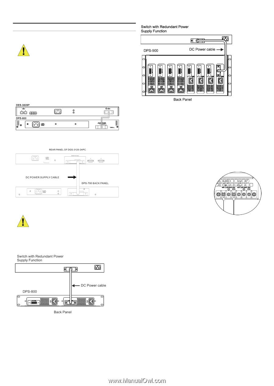
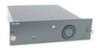
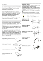
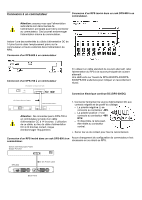
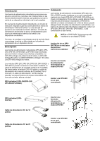
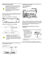
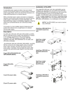
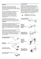
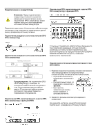
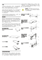
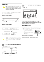
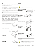
Switch Connection Caution: The redundant power supply should be disconnected from its power source before connecting to the switch. Directly connecting a powered RPS to the switch may cause damage to the switch's internal power supply. Insert one end of the 14-pin DC power cable into the receptacle on the switch and the other end into the redundant power supply. Connecting a DPS-600 to a switch Connecting a DPS-700 to a switch Using a standard AC power cable, connect the redundant power supply to the main AC power source. A green LED on the front of the DPS-200/DPS-300/DPS-500/DPS-600 will glow to indicate a successful connection. Connecting DC Power (DPS-500DC) Caution: Do not connect the DPS-700 to the switch using the 14-pin DC power cable. The equipment may be damaged if using this cable instead of the correct 22-pin DC power cable. 1. Firmly attach the DC power source to the negative and positive contacts on the wiring assembly. The negative pole (-) connects to the -48V contact. The positive pole (+) connects to the -48V RTN contact. If available, an earth ground may be connected to the center contact post. 2. Tighten the contact screws to secure the connection. No change in switch configuration is necessary when connecting to the RPS. Connecting a single RPS in a DPS-800 rack to a switch Connecting a single RPS in a DPS-900 rack to a switch
-
 1
1 -
2
-
3
-
4
-
5
-
 6
6 -
 7
7 -
 8
8 -
 9
9 -
 10
10 -
 11
11 -
 12
12 -
 13
13 -
 14
14 -
 15
15 -
 16
16 -
17
-
18
-
19
-
20
 |
 |