D-Link DSN-4100 Hardware Reference Guide for DSN-4000 - Page 26
Connecting the AC Power Cords, Connect any DSN-4000 JBOD Expansion Arrays optional
 |
View all D-Link DSN-4100 manuals
Add to My Manuals
Save this manual to your list of manuals |
Page 26 highlights
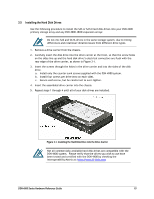
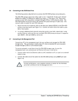
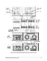
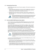
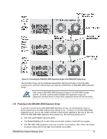
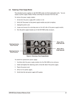
3.8 Connecting the AC Power Cords The DSN-4X00 storage system has two AC power receptacles. Both must be connected to an AC power outlet. 1. Plug the female end of one power cord into one of the 3-pronged power connectors on the back of the DSN-4X00 storage array. Plug the other end of the power cord into a working AC power outlet that is not controlled by a wall switch. 2. Repeat the previous step using the second power cable and power receptacle on the DSN-4X00 storage array. For best results, the second power receptacle should be on a different circuit. Although the DSN-4X00 storage array can operate temporarily with only one AC power connection, an audio alarm will sound until both power supply units are powered on or until the MUTE button is pressed. 3.9 Connect any DSN-4000 JBOD Expansion Arrays (optional) You can connect up to four additional DSN-4000 JBOD expansion array with 16 drive bays each to increase the physical storage capacity of your DSN-4X00 storage system, up to a maximum of 80 drives. If the DSN-4000 JBOD expansion array will be installed on a desktop or shelf, locate the expansion array close to the DSN-4X00 primary array, with sufficient ventilation space between the expansion array and any other objects in the vicinity. Do not block the air vents on the front and back of the DSN-4000 JBOD expansion array enclosure. Install the cables and power cords according to the procedures in the following sections. If the DSN-4X00 primary array will be mounted in a rack, mount the DSN-4000 JBOD expansion array in the same rack, either above or below the primary array. For information about installing the system in a rack, refer to Appendix B and the documentation for the rack. The rack cabinet must provide sufficient airflow to the front and back of the DSN-4000 JBOD expansion array to maintain correct cooling. It must include ventilation sufficient to exhaust the heat generated by equipment installed in the rack. To connect the first DSN-4000 JBOD expansion array to the DSN-4X00 primary array, use the following procedure and refer to Figure 3-3. 1. Facing the rear of the primary array, connect one end of the expansion chassis cable that was supplied with the DSN-4000 JBOD array to the expansion connector labeled SAS EXP and ensure that it snaps fully into place. 2. To attach additional expansion arrays, use the expansion cable that was supplied with the DSN-4000 JBOD array between the SAS OUT connector (diamond icon) on one expansion array and the SAS IN connector (circle icon) on the next expansion array. 18 Chapter 3 Installing the DSN-4000 Series PrimaryArray
-
 1
1 -
2
-
3
-
4
-
5
-
6
-
7
-
8
-
9
-
10
-
11
-
12
-
13
-
14
-
15
-
16
-
17
-
18
-
19
-
20
-
 21
21 -
 22
22 -
 23
23 -
 24
24 -
 25
25 -
 26
26 -
 27
27 -
 28
28 -
 29
29 -
 30
30 -
 31
31 -
32
-
33
-
34
-
35
-
36
-
37
-
38
 |
 |