D-Link DSN-5000-10 Hardware Reference Guide for DSN-5000-10 - Page 38
Connecting DSN-5000-10 Expansion Arrays to a DSN-5210-10 or 5410-10 Primary Array
 |
UPC - 790069324024
View all D-Link DSN-5000-10 manuals
Add to My Manuals
Save this manual to your list of manuals |
Page 38 highlights
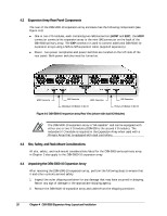
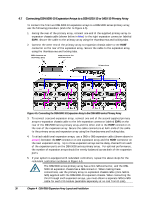
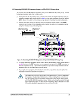
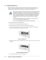
4.7 Connecting DSN-5000-10 Expansion Arrays to a DSN-5210-10 or 5410-10 Primary Array To connect the first two DSN-5000-10 expansion arrays to a DSN-5000 series primary array, use the following procedure (and refer to Figure 4-5). 1. Facing the rear of the primary array, connect one end of the supplied primary array-toexpansion chassis cable (shown below in blue) to the right expansion connector labeled EXP0. Secure the cable to the primary array using the thumbscrews and locking tabs. 2. Connect the other end of the primary array-to-expansion chassis cable to the HOST connector on the rear of the expansion array. Secure the cable to the expansion array using the thumbscrews and locking tabs. EXP1 Connector on the Primary Array EXP0 Connector the on Primary Array Primary Array First Expansion Array Figure 4-5. Connecting the DSN-5000-10 Expansion Array to the DSN-5000 series Primary Array 3. To connect a second expansion array, connect one end of the second supplied primary array-to-expansion chassis cable to the left expansion connector labeled EXP1 on the rear of the DSN-5000 series primary array and the other end to the HOST connector on the rear of the expansion array. Secure the cable connectors at both ends of the cable to the primary array and expansion array using the thumbscrews and locking tabs. 4. To attach additional expansion arrays, use a SAS-to-SAS expansion cable (shown above in purple) between the EXP connector on one expansion array and the HOST connector on the next expansion array. Up to three expansion arrays can be daisy-chained from each of the expansion ports on the DSN-5000 series primary array. For optimal performance, the number of expansion arrays should be evenly balanced across both of the expansion ports. 5. If your system is equipped with redundant controllers, repeat the above steps for the redundant controllers as shown in Figure 4-5. The DSN-5000 series primary array has a mini-SAS connector, and the DSN5000-10 expansion chassis has a SAS connector. When making these connections, use the primary array-to-expansion chassis cable (mini-SAS to SAS) supplied with the DSN-5000-10 expansion chassis. When connecting the third through sixth expansion arrays, you must obtain a separate SAS-to-SAS cable for each I/O module (available separately at no cost from D-Link). 30 Chapter 4 DSN-5000 Expansion Array Layout and Installation
-
 1
1 -
2
-
3
-
4
-
5
-
6
-
7
-
8
-
9
-
10
-
11
-
12
-
13
-
14
-
15
-
16
-
17
-
18
-
19
-
20
-
21
-
22
-
23
-
24
-
25
-
26
-
27
-
28
-
29
-
30
-
31
-
32
-
 33
33 -
 34
34 -
 35
35 -
 36
36 -
 37
37 -
 38
38 -
 39
39 -
 40
40 -
 41
41 -
 42
42 -
 43
43 -
44
-
45
-
46
-
47
-
48
-
49
-
50
-
51
-
52
 |
 |
