D-Link DSS 5 Product Manual - Page 16
Pecification
 |
UPC - 790069219153
View all D-Link DSS 5 manuals
Add to My Manuals
Save this manual to your list of manuals |
Page 16 highlights
RJ-45 PIN SPECIFICATION The following diagram and tables show the standard RJ-45 receptacle/connector and their pin assignments. RJ-45 Connector pin assignment Contact Media Direct Interface Signal 1 Tx + (transmit) 2 Tx - (transmit) 3 Rx + (receive) 4 Not used 5 Not used 6 Rx - (receive) 7 Not used 8 Not used RJ-45 pin assignment Standard RJ-45 receptacle/connector 14
-
 1
1 -
2
-
3
-
4
-
5
-
6
-
7
-
8
-
9
-
10
-
 11
11 -
 12
12 -
 13
13 -
 14
14 -
 15
15 -
 16
16 -
 17
17 -
 18
18 -
 19
19 -
 20
20
 |
 |

14
RJ-45 P
IN
S
PECIFICATION
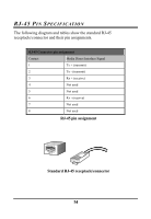
The following diagram and tables show the standard RJ-45
receptacle/connector and their pin assignments.
RJ-45 Connector pin assignment
Contact
Media Direct Interface Signal
1
Tx + (transmit)
2
Tx - (transmit)
3
Rx + (receive)
4
Not used
5
Not used
6
Rx - (receive)
7
Not used
8
Not used
RJ-45 pin assignment
Standard RJ-45 receptacle/connector