D-Link DXS-1210-12SC User Guide
D-Link DXS-1210-12SC Manual
 |
View all D-Link DXS-1210-12SC manuals
Add to My Manuals
Save this manual to your list of manuals |
D-Link DXS-1210-12SC manual content summary:
- D-Link DXS-1210-12SC | User Guide - Page 1
DXS-1210 Series L2 10 Gigabit Ethernet Switch Series Ver. 1.01 - D-Link DXS-1210-12SC | User Guide - Page 2
D-Link DXS-1210 Series User Manual Table of Contents Table of Contents ...i About This Guide...1 Terms/Usage...1 Copyright and Trademarks ...1 1 Product Introduction ...2 DXS-1210-10TS...2 Front Panel ...3 Rear Panel...3 DXS-1210-12TC...3 Front Panel ...3 Rear Panel...4 DXS-1210-12SC ...4 Front - D-Link DXS-1210-12SC | User Guide - Page 3
Link DXS-1210 Series User Manual Configuration Upgrade & Backup > Configuration Backup to HTTP 15 Configuration Upgrade & Backup > Configuration Backup to TFTP 15 Log Backup > Log Backup to HTTP...15 Log Backup >Log Backup to TFTP ...15 Ping ...16 Reset ...16 Reboot System ...16 Tool Bar > Smart - D-Link DXS-1210-12SC | User Guide - Page 4
Link DXS-1210 Series User Manual L2 Features > STP > MST Configuration Identification 41 L2 Features > STP > STP Instance ...41 L2 Features > STP > MSTP Port Information 42 L2 Features > Loopback Detection ...42 L2 Features > Link Features > IPv6 Default Route ...62 QoS > Port Default CoS ...62 - D-Link DXS-1210-12SC | User Guide - Page 5
Link DXS-1210 Series User Manual Security > Trusted Host...90 Security > Traffic Segmentation Settings 91 Security > Storm Control Settings ...91 Security > DoS Attack Prevention Settings 92 Security > SSL > SSL Global Setting ...93 Security > SSL > SSL Service show tech-support ...108 Appendix - D-Link DXS-1210-12SC | User Guide - Page 6
About This Guide D-Link DXS-1210 Series User Manual About This Guide This guide provides installation and instructions for the D-Link 10 Gigabit Ethernet L2 Switch (DXS-121012TC/12SC/10TS), Note: The model you have purchased may appear slightly different from the illustrations shown in the - D-Link DXS-1210-12SC | User Guide - Page 7
Link DXS-1210 Series User Manual 1 Product Introduction Thank you and congratulations on your purchase of D-Link DXS-1210 Series Switch. D-Link Switch IP address, resetting the settings to factory defaults, setting the administrator password, rebooting the Switch, or upgrading the Switch firmware by - D-Link DXS-1210-12SC | User Guide - Page 8
1 Product Introduction Front Panel D-Link DXS-1210 Series User Manual Figure 1.1 - DXS-1210-10TS Front Panel Power LED : The back to the default configuration and all changes will be lost. Port Link/Act/Speed LED (1-8, 9F, 10F): The port LEDs indicate a network link through the corresponding port - D-Link DXS-1210-12SC | User Guide - Page 9
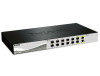
Rear Panel D-Link DXS-1210 Series User Manual Figure 1.4 - DXS-1210-12TC Rear Panel Power: Connect the AC power cord to this port. DXS-1210-12SC 10-Port 10G SFP+ fiber port and 2-port 10GBASE-T/SFP + combo port L2 10 Gigabit Ethernet Switch. Front Panel Figure 1.5 - DXS-1210-12SC Front Panel - D-Link DXS-1210-12SC | User Guide - Page 10
Manual 2 Hardware Installation This chapter provides unpacking and installation information for the D-Link DXS-1210 Series Switch. Safety Cautions To reduce the risk of bodily injury, electrical shock, fire,and damage to the equipment, observe the following precautions: • Observe and follow service - D-Link DXS-1210-12SC | User Guide - Page 11
in the User Manual to make sure all items are present and undamaged. If any item is missing or damaged, please contact your local D-Link reseller for replacement. One D-Link DXS-1210 Series switch One Multilingual Getting Started Guide User Guide CD with DNA (D-Link Network Assistant) Program - D-Link DXS-1210-12SC | User Guide - Page 12
2 Hardware Installation D-Link DXS-1210 Series User Manual Then, use the screws provided with the equipment rack to mount the switch in the rack. Figure 2.3 - Mount the Switch in the rack or chassis - D-Link DXS-1210-12SC | User Guide - Page 13
3 Getting Started D-Link DXS-1210 Series User Manual 3 Getting Started This chapter introduces the management interface of D-Link DXS-1210 Series Switch. Management Options The D-Link DXS-1210 Series. Switch can be managed through any port by using the Web-based Management, or through any PC using - D-Link DXS-1210-12SC | User Guide - Page 14
3 Getting Started D-Link DXS-1210 Series User Manual Figure 3.2 -Enter the IP address 10.90.90.90 in the web browser NOTE: The switch's factory default IP address is 10.90.90.90 with a subnet mask of 255.0.0.0 and a default gateway of 0.0.0.0. When the following login dialog box appears, enter the - D-Link DXS-1210-12SC | User Guide - Page 15
4 Configuration D-Link DXS-1210 Series User Manual 4 Configuration The features and functions of the D-Link DXS-1210 Series Switch can be configured for optimum use through the Web-based Management Utility. Smart Wizard Configuration After a successful login, the Smart Wizard will guide you - D-Link DXS-1210-12SC | User Guide - Page 16
4 Configuration D-Link DXS-1210 Series User Manual Figure 4.2 - SNMP Settings in Smart Wizard User Accounts Settings The the configuration. Figure 4.3 - User Accounts Setting in Smart Wizard Web-based Management After clicking the Exit button in the Smart Wizard you will see the screen below: 11 - D-Link DXS-1210-12SC | User Guide - Page 17
4 Configuration D-Link DXS-1210 Series User Manual Figure 4.4 - Web-based Management The above image is the Web-based Management screen. The three At the upper right corner of the screen the username and current IP address will be displayed. Under the username is the Logout button. Click this to - D-Link DXS-1210-12SC | User Guide - Page 18
4 Configuration D-Link DXS-1210 Series User Manual Figure 4.6 - Save Configuration Destination: Select the configuration destination to Firmware Backup and Upgrade. Figure 4.7 - Tool Menu Firmware Information Display the firmware information for the 2-image ID. Figure 4.8 - Tool Menu > Firmware - D-Link DXS-1210-12SC | User Guide - Page 19
4 Configuration D-Link DXS-1210 Series User Manual Note: The Switch will reboot after restoring, and all current configurations will be lost Firmware Upgrade & Backup > Firmware Upgrade from TFTP Upgrade firmware by using TFTP. Enter the TFTP IP address, source URL, and select a Destination URL. - D-Link DXS-1210-12SC | User Guide - Page 20
4 Configuration D-Link DXS-1210 Series User Manual Figure 4.15 - Tool Menu > Configuration Upgrade & Backup > Configuration Upgrade & Backup > Configuration Backup to TFTP TFTP Server IP: Select IPv4 or IPv6 and enter the IP address. Source: Select the source configuration file. Startup-config: - D-Link DXS-1210-12SC | User Guide - Page 21
D-Link DXS-1210 Series User Manual Ping Smart Wizard if you wish to make any changes. Tool Bar > Online Help The Online Help provides two ways of online support: D-link Support Site will lead you to the D-Link website where you can find online resources such as updated firmware; User Guide - D-Link DXS-1210-12SC | User Guide - Page 22
4 Configuration D-Link DXS-1210 Series User Manual Figure 4.24 - User Guide Micro Site 17 - D-Link DXS-1210-12SC | User Guide - Page 23
4 Configuration D-Link DXS-1210 Series User Manual Function Tree All configuration options on the switch are provides an overview of the switch, including essential information such as firmware & hardware information, and IP settings. Figure 4.26 - Device Information System > System Information - D-Link DXS-1210-12SC | User Guide - Page 24
4 Configuration D-Link DXS-1210 Series User Manual Figure 4.27 - System > System Information System > Port port. Auto Downgrade: To enable or disable automatically downgrading advertised speed in case a link cannot be established at the available speed. Flow Control: Select On or Off. Ports - D-Link DXS-1210-12SC | User Guide - Page 25
4 Configuration D-Link DXS-1210 Series User Manual Figure 4.29 - System > Port Configuration > Port Status System > Port Configuration > Error Disable Settings The Error Disable Settings page allows you to configure the sending of - D-Link DXS-1210-12SC | User Guide - Page 26
Link DXS-1210 Series User Manual System > Port Configuration > Jumbo Frame The Jumbo Frame page allows you to view and configure the Jumbo Frame size and settings. Jumbo frames are Ethernet frames with more than 1,518 bytes of payload. The Switch supports will be used. The default option is VLAN. - D-Link DXS-1210-12SC | User Guide - Page 27
D-Link DXS-1210 Series User Manual Figure 4.33 - System > System Log > System Log Server Settings IP Address: Select and enter the IPv4 address or IPv6 Address. UDP Port (514 or 1024-65535): Enter the system log server's UDP port number. This value must be 514 or between 1024 and 65535. The default - D-Link DXS-1210-12SC | User Guide - Page 28
4 Configuration D-Link DXS-1210 Series User Manual Figure 4.36 - System > Time and SNTP > Time Zone Settings saving time will end. Offset - Enter the number of minutes to add during daylight saving time. The default value is 60. The range of this offset is 30, 60, 90 and 120. The Date Setting - D-Link DXS-1210-12SC | User Guide - Page 29
4 Configuration D-Link DXS-1210 Series User Manual System > Time and SNTP > SNTP Settings The SNTP Interval (30-99999): Enter the poll interval. The value is from 30 to 99999 seconds. The default interval is 720 seconds. Click the Apply button to save your settings. SNTP Server Setting: IPv4 - D-Link DXS-1210-12SC | User Guide - Page 30
4 Configuration D-Link DXS-1210 Series User Manual Management > User Accounts Settings The User Accounts Settings page allows you to create and . Use SNMP to configure system features for proper operation, monitor performance and detect potential problems on the Switch or your local network. 25 - D-Link DXS-1210-12SC | User Guide - Page 31
Link DXS-1210 Series User Manual Managed devices that support used to access this information over the network. The default SNMP global state is disabled. Select Enable and 0 and 65535. Trap Source Interface: Specify the interface whose IP address will be used as the source address for sending the - D-Link DXS-1210-12SC | User Guide - Page 32
4 Configuration D-Link DXS-1210 Series User Manual Figure 4.43 - Management > SNMP > SNMP View Table Settings View Name: string created can read from, and write to the contents of the MIBs on the Switch. IP Access-List Name: Enter the name of the standard access list to control the user to use - D-Link DXS-1210-12SC | User Guide - Page 33
Link DXS-1210 Series User Manual does not support any security features. SNMPv2c - SNMPv2 supports both centralized and for packets sent between the Switch and SNMP manger. IP Address-List Name: Read View Name: Enter a Default to change back to the default value. Figure 4.46 - Management > SNMP > - D-Link DXS-1210-12SC | User Guide - Page 34
4 Configuration D-Link DXS-1210 Series User Manual Management > SNMP > SNMP User Table Settings The SNMP DES (DES-56) standard. This field will require the user to enter a key. IP Address-List Name: Enter the standard IP access control list (ACL) to associate with the user. Click Add to create a - D-Link DXS-1210-12SC | User Guide - Page 35
Link DXS-1210 Series User Manual Figure 4.48 - Management > SNMP > SNMP Host Table Settings Host IPv4/IPv6 Address: Select IPv4 or IPv6 and specify the IP will be encrypted. UDP Port (0-65535): Enter the UDP port number. The default trap UDP port number is 162. The range of UDP port numbers is from - D-Link DXS-1210-12SC | User Guide - Page 36
D-Link DXS-1210 Series User Manual Index taken from the ports. The field range is 1-3600. The default is 1800 seconds (equal to 30 minutes). Owner: Displays the configure the network alarms. Network alarms occur when a network problem or event is detected. Figure 4.52 - Management > RMON - D-Link DXS-1210-12SC | User Guide - Page 37
4 Configuration D-Link DXS-1210 Series User Manual Interval (1 ~ 2^31-1): Defines the alarm interval time Click Add to add a new RMON event. Management > Telnet/Web The Telnet/Web page allows you to configure Telnet and Web settings on the Switch. Telnet Settings: Figure 4.54 - Management > - D-Link DXS-1210-12SC | User Guide - Page 38
D-Link DXS-1210 Series User Manual Telnet State: Select to enable or disable the configuration through Telnet. Port (1-65535): Enter the TCP port number used for Telnet management of the Switch. The "well-known" TCP port for the Telnet protocol is 23. Click Apply to save your settings. Web - D-Link DXS-1210-12SC | User Guide - Page 39
4 Configuration D-Link DXS-1210 Series User Manual D-Link Discovery Protocol State: Enter the enable or disable the D-Link Discovery Protocol state. Report Timer: Specify the interval in seconds between two consecutive DDP report messages. Options to choose from are 30, 60, 90,120, - D-Link DXS-1210-12SC | User Guide - Page 40
4 Configuration D-Link DXS-1210 Series User Manual Enter a page number and click the Go button to value must be between 10 and 1000000 seconds. Entering 0 will disable MAC address aging. By default, this value is 300 seconds. Aging Destination Hit: Select to enable or disable the aging destination - D-Link DXS-1210-12SC | User Guide - Page 41
4 Configuration D-Link DXS-1210 Series User Manual Port: Select the port that will be used for this configuration. VID (1-4094): Enter the VLAN ID that will be used for this configuration. MAC - D-Link DXS-1210-12SC | User Guide - Page 42
4 Configuration D-Link DXS-1210 Series User Manual Figure 4.64 - L2 Features > VLAN Interface Unit: Select the switch unit that will be used for this configuration. Click the VLAN Detail button to view - D-Link DXS-1210-12SC | User Guide - Page 43
4 Configuration D-Link DXS-1210 Series User Manual L2 Features > STP > STP Global Settings The Switch STP instance, the same port can be placed in the Forwarding state in another STP instance. By default, Rapid Spanning Tree is disabled. If enabled, the Switch will listen for BPDU packets and its - D-Link DXS-1210-12SC | User Guide - Page 44
4 Configuration D-Link DXS-1210 Series User Manual STP Priority: STP (0-61440): Enter the STP priority value. This value is between 0 and 61440. By default, this value is 32768. The lower the value, the higher the priority. Click the Apply button to save your settings. STP Configuration: Bridge - D-Link DXS-1210-12SC | User Guide - Page 45
4 Configuration D-Link DXS-1210 Series User Manual Figure 4.68 - L2 Features > STP > STP Port the interface receives a BPDU later, its operation state changes to the non-port-fast state. By default, this option is Network. TCN Filter: Select to enable or disable the TCN filter option. Enabling - D-Link DXS-1210-12SC | User Guide - Page 46
4 Configuration D-Link DXS-1210 Series User Manual Click Apply button to save your settings. L2 Features > STP > MST Configuration Identification Multiple Spanning Tree (MSTP) provides various load balancing scenarios by allowing multiple - D-Link DXS-1210-12SC | User Guide - Page 47
4 Configuration D-Link DXS-1210 Series User Manual Click the Edit button to re-configure the -down list. Interval (1-32767): Set a Loop Detection Interval between 1 and 32767 seconds. The default is 2 seconds. Trap State: Select to enable or disable the loopback detection trap state. Action - D-Link DXS-1210-12SC | User Guide - Page 48
4 Configuration D-Link DXS-1210 Series User Manual State: Use the drop-down menu to toggle between Enabled and Disabled. Default is disabled. Click Apply to save your settings. L2 Features > Link Aggregation The Link Aggregation page allows you to view and configure the link aggregation settings. - D-Link DXS-1210-12SC | User Guide - Page 49
4 Configuration D-Link DXS-1210 Series User Manual Figure 4.74 - L2 Features > L2 Multicast Control > IGMP Snooping > IGMP Snooping Settings Global Settings: Global State: Select to enable or disable the IGMP Snooping global - D-Link DXS-1210-12SC | User Guide - Page 50
4 Configuration D-Link DXS-1210 Series User Manual Click the Modify button to edit the information in the following window: Figure 4.76 L2 Features > L2 Multicast Control > IGMP Snooping > IGMP Snooping - Modify The - D-Link DXS-1210-12SC | User Guide - Page 51
4 Configuration D-Link DXS-1210 Series User Manual VID (1-4094): Enter the VLAN ID. Group Address: Enter the IP multicast group address. ): Specify the VLAN ID. Group Address: Click the radio button and enter an IP multicast group address. Click the Find button to locate a specific entry based on - D-Link DXS-1210-12SC | User Guide - Page 52
4 Configuration D-Link DXS-1210 Series User Manual L2 Features > L2 Multicast Control > IGMP Snooping > IGMP Snooping Statistics Settings The IGMP Snooping Statistics Settings page allows you to clear and display the IGMP - D-Link DXS-1210-12SC | User Guide - Page 53
4 Configuration D-Link DXS-1210 Series User Manual VID (1-4094): Enter the VLAN ID to be searched. Click the Find button to locate a specific entry based on the information entered. Click the Find - D-Link DXS-1210-12SC | User Guide - Page 54
4 Configuration D-Link DXS-1210 Series User Manual Querier State: Select to enable or disable the querier Groups Table are described below: VID (1-4094): Enter the VLAN ID. Group Address: Enter the IP multicast group address. Click the Find Snooping button to locate a specific entry based on the - D-Link DXS-1210-12SC | User Guide - Page 55
4 Configuration D-Link DXS-1210 Series User Manual Figure 4.84 - L2 Features > L2 Multicast Control > MLD Snooping > MLD Snooping Mrouter Settings VID (1-4094): Enter the VLAN ID. Configuration: Select the port configuration. Available - D-Link DXS-1210-12SC | User Guide - Page 56
4 Configuration D-Link DXS-1210 Series User Manual Figure 4.86 - L2 Features > L2 Multicast Control > Multicast topology by obtaining the MIB information in each LLDP device. The LLDP function is enabled by default. Figure 4.87 - L2 Features > LLDP > LLDP Global Settings LLDP Global Settings: LLDP - D-Link DXS-1210-12SC | User Guide - Page 57
4 Configuration D-Link DXS-1210 Series User Manual through ports. For the receiving of LLDP Enables transmitting and receiving LLDP packets. This is the default value. Disabled - Disables LLDP on the port. IP Subtype: Select the type of the IP address information to be sent. Options to choose from - D-Link DXS-1210-12SC | User Guide - Page 58
4 Configuration D-Link DXS-1210 Series User Manual and IPv6. Action: Select to remove or add the action field. Address: Enter the IP address to be Displays the managed address subtype. (e.g., MAC or IPv4) Address: Displays the IP address. IF Type: Displays the IF Type. OID: Displays the SNMP OID. - D-Link DXS-1210-12SC | User Guide - Page 59
4 Configuration D-Link DXS-1210 Series User Manual L2 Features > LLDP > LLDP Dot1 TLVs Settings This LLDP Dot1 TLVs Settings page allows you to configure an individual port or group of ports to - D-Link DXS-1210-12SC | User Guide - Page 60
4 Configuration D-Link DXS-1210 Series User Manual MAC/PHY Configuration/Status: Select whether the MAC/ Maximum Frame Size configured on the port. Power via MDI: Advertises the Power via MDI implementations supported by the port. The possible field values are: Enabled - Enables the Power via MDI - D-Link DXS-1210-12SC | User Guide - Page 61
4 Configuration D-Link DXS-1210 Series User Manual Figure 4.94 - L2 Features > LLDP > LLDP Statistics Information The following information can be viewed: LLDP Statistics Information: Displays the counters that refer to the whole - D-Link DXS-1210-12SC | User Guide - Page 62
4 Configuration D-Link DXS-1210 Series User Manual Figure 4.95 - L2 Features > LLDP > LLDP Local Port Information Port: Displays the port number. Port ID Subtype: Displays the port ID subtype. Port ID: Displays - D-Link DXS-1210-12SC | User Guide - Page 63
Link DXS-1210 Series User Manual Time Timeout(min): Specifies the aging time of the ARP entry. The default is 5 minutes. Click the Apply button to save your settings. regarding each interface, including which IP address was mapped to what MAC address. Enter an IP Address or Hardware Address and then - D-Link DXS-1210-12SC | User Guide - Page 64
Link DXS-1210 Series User Manual Figure 4.100 - L3 Features > ARP > ARP Table Interface VLAN (1-4094): Select and enter the interface's VLAN ID. IP address: Select and enter the IP address to be displayed. Mask: Enter the mask address for the specified IP the VLAN ID of IP interface. Click Apply for - D-Link DXS-1210-12SC | User Guide - Page 65
4 Configuration D-Link DXS-1210 Series User Manual Click the Back button to return to the previous window. State: Select to enable or disable the IPv4 interface's global state. Click the Apply button to save your settings. IP Settings: Get IP From: Select the IP from option. The values are Static - D-Link DXS-1210-12SC | User Guide - Page 66
4 Configuration D-Link DXS-1210 Series User Manual Figure 4.105 - L3 Features > IPv6 Interface Interface VLAN (1-4094): Enter the VLAN ID of IP interface. Click Apply for the settings to take effect. Click the Find button to display the specific entry. Click the Detail button to view and - D-Link DXS-1210-12SC | User Guide - Page 67
4 Configuration D-Link DXS-1210 Series User Manual Figure 4.108 - L3 Features > IPv6 Interface - DHCPv6 exist. L3 Features > IPv6 Default Route The IPv6 Default Route is used to configure the IPv6 static or default routes. Figure 4.110 - L3 Features > IPv6 Default Route Interface VLAN (1-4094): - D-Link DXS-1210-12SC | User Guide - Page 68
D-Link DXS-1210 Series User Manual Figure 4.111 - QoS > Port Default CoS From Port / To Port: Select the range of ports to be configured. Default CoS: Select the default CoS option for the specified ports. The values are from 0 to 7. Click the Override check box to apply the port's default CoS - D-Link DXS-1210-12SC | User Guide - Page 69
4 Configuration D-Link DXS-1210 Series User Manual Figure 4.113 - QoS > Queue Settings From Port / To Port: Select the range of ports to be configured. Queue ID: Select the queue id value. The - D-Link DXS-1210-12SC | User Guide - Page 70
4 Configuration D-Link DXS-1210 Series User Manual Figure 4.115 - QoS > Port Rate Limiting From Port / To Port: Select the range of ports to be configured. Direction: Select the direction. Available options are - D-Link DXS-1210-12SC | User Guide - Page 71
4 Configuration D-Link DXS-1210 Series User Manual Figure 4.116 - QoS > Queue Rate Limiting From Port / To Port: Select the range of ports to be configured. Queue ID: Select the queue ID for - D-Link DXS-1210-12SC | User Guide - Page 72
4 Configuration D-Link DXS-1210 Series User Manual QoS > DSCP CoS Mapping The DSCP CoS Mapping page allows you to view and configure the DSCP CoS mapping settings. Figure 4.118 - QoS > DSCP CoS - D-Link DXS-1210-12SC | User Guide - Page 73
4 Configuration D-Link DXS-1210 Series User Manual Figure 4.120 - ACL > ACL Configuration Wizard - Packet Type MAC: Select to create a MAC ACL. IPv4: Select to create aarp, appletalk, decent-iv, etype-6000, etype-8042, lat, lavc-sca, mop-console, mop-dump, vines-echo, vines-ip, xnsidp, and arp. 68 - D-Link DXS-1210-12SC | User Guide - Page 74
4 Configuration D-Link DXS-1210 Series User Manual Ethernet Type (0x600-0xFFFF): Enter the Ethernet Options to choose from are TCP, UDP, ICMP, EIGRP, ESP, GRE, IGMP, OSPF, PIM, VRRP, IP-in-IP, PCP, Protocol ID, and None. After selecting the TCP option as the Protocol Type then Click the associated - D-Link DXS-1210-12SC | User Guide - Page 75
4 Configuration D-Link DXS-1210 Series User Manual Figure 4.123 - ACL > ACL Configuration Wizard - Create IPv4 ACL-TCP Source: Select the source information. The values are Any, Host and IP. Destination: Select the destination information. The values are Any, Host and IP. Source Port: Select the - D-Link DXS-1210-12SC | User Guide - Page 76
4 Configuration D-Link DXS-1210 Series User Manual Figure 4.124 - ACL > ACL Configuration Wizard - Create IPv4 ACL-UDP Source: Select the source information. The values are Any, Host and IP. Destination: Select the destination information. The values are Any, Host and IP. Source Port: Select the - D-Link DXS-1210-12SC | User Guide - Page 77
D-Link DXS-1210 Series User Manual Figure 4.125 - ACL > ACL Configuration Wizard - Create IPv4 ACL-ICMP Source: Select the source information. The values are Any, Host and IP. Destination: Select the destination information. The values are Any, Host and IP. IP Precedence: Select the IP precedence - D-Link DXS-1210-12SC | User Guide - Page 78
4 Configuration D-Link DXS-1210 Series User Manual Figure 4.126 - ACL > ACL Configuration Wizard - Create IPv4 ACL-EIGRP Source: Select the source information. The values are Any, Host and IP. Destination: Select the destination information. The values are Any, Host and IP. Fragments: Specify the - D-Link DXS-1210-12SC | User Guide - Page 79
D-Link DXS-1210 Series User Manual Figure 4.127 - ACL > ACL Configuration Wizard - Create IPv4 ACL-ESP Source: Select the source information. The values are Any, Host and IP. Destination: Select the destination information. The values are Any, Host and IP. IP Precedence: Select the IP precedence - D-Link DXS-1210-12SC | User Guide - Page 80
4 Configuration D-Link DXS-1210 Series User Manual Figure 4.129 - ACL > ACL Configuration Wizard - Create IPv4 ACL-IGMP Fragments: Select the Fragments option to include packet fragment filtering. Source: Select the source information. The values are Any, Host and IP. Destination: Select the - D-Link DXS-1210-12SC | User Guide - Page 81
D-Link DXS-1210 Series User Manual Fragments: Select the Fragments option to include packet fragment filtering. Source: Select the source information. The values are Any, Host and IP. Destination: Select the destination information. The values are Any, Host and IP. IP Precedence: Select the IP - D-Link DXS-1210-12SC | User Guide - Page 82
4 Configuration D-Link DXS-1210 Series User Manual Figure 4.132 - ACL > ACL Configuration Wizard - Create IPv4 ACL-VRRP Fragments: Select the Fragments option to include packet fragment filtering. Source: Select the source information. The values are Any, Host and IP. Destination: Select the - D-Link DXS-1210-12SC | User Guide - Page 83
D-Link DXS-1210 Series User Manual Fragments: Select the Fragments option to include packet fragment filtering. Source: Select the source information. The values are Any, Host and IP. Destination: Select the destination information. The values are Any, Host and IP. IP Precedence: Select the IP - D-Link DXS-1210-12SC | User Guide - Page 84
4 Configuration D-Link DXS-1210 Series User Manual Figure 4.135 - ACL > ACL Configuration Wizard - Create IPv4 ACL-Protocol ID Fragments: Select the Fragments option to include packet fragment filtering. Source: Select the source information. The values are Any, Host and IP. Destination: Select - D-Link DXS-1210-12SC | User Guide - Page 85
D-Link DXS-1210 Series User Manual Fragments: Select the Fragments option to include packet fragment filtering. Source: Select the source information. The values are Any, Host and IP. Destination: Select the destination information. The values are Any, Host and IP. IP Precedence: Select the IP - D-Link DXS-1210-12SC | User Guide - Page 86
4 Configuration D-Link DXS-1210 Series User Manual Figure 4.138 - ACL > ACL Configuration Wizard - Create IPv6 ACL-UDP Source Port: Select the source port value. Destination Port: Select the destination port value. Source: Select the source information. The values are Any, Host and IP. Destination - D-Link DXS-1210-12SC | User Guide - Page 87
4 Configuration D-Link DXS-1210 Series User Manual Figure 4.139- ACL > ACL Configuration Wizard - Create IPv6 ACL-ICMP Source: Select the source information. The values are Any, Host and IP. Destination: Select the destination information. The values are Any, Host and IP. DSCP (0-63): Select the - D-Link DXS-1210-12SC | User Guide - Page 88
4 Configuration D-Link DXS-1210 Series User Manual Figure 4.140 - ACL > ACL Configuration Wizard - Create IPv6 ACL-Protocol ID Source: Select the source information. The values are Any, Host and IP. Destination: Select the destination information. The values are Any, Host and IP. DSCP (0-63): - D-Link DXS-1210-12SC | User Guide - Page 89
4 Configuration D-Link DXS-1210 Series User Manual Figure 4.142 - ACL > ACL Configuration Wizard - Create IPv6 ACL-PCP Source: Select the source information. The values are Any, Host and IP. Destination: Select the destination information. The values are Any, Host and IP. DSCP (0-63): Enter the - D-Link DXS-1210-12SC | User Guide - Page 90
4 Configuration D-Link DXS-1210 Series User Manual DSCP (0-63): Enter the DSCP value. And the range is Select the source information. The values are Any, Host and IP. Destination: Select the destination information. The values are Any, Host and IP. DSCP (0-63): Enter the DSCP value. And the range - D-Link DXS-1210-12SC | User Guide - Page 91
Link DXS-1210 Series User Manual ACL > ACL Access List The ACL Access List page allows you to view and configure the ACL access list settings. Figure 4.146 - ACL > ACL Access List ACL Type: Select the ACL profile type to find. Options to choose from are All, IP from are All, IP ACL, IPv6 ACL, - D-Link DXS-1210-12SC | User Guide - Page 92
4 Configuration D-Link DXS-1210 Series User Manual After clicking the Please Select button, the following page will appear Address (1-6656): Enter the maximum number of secure MAC addresses allowed. If not specified, the default value is No Limit. The valid range is from 1 to 6656. Tick the No - D-Link DXS-1210-12SC | User Guide - Page 93
4 Configuration D-Link DXS-1210 Series User Manual Security > Port Security > Port Security Port Settings The exactly after the time specified and is removed from the secure address list. This is the default type. Select Inactivity so that the secure addresses on this port age out only if there - D-Link DXS-1210-12SC | User Guide - Page 94
4 Configuration D-Link DXS-1210 Series User Manual VID (1-4094): Enter the VLAN ID. The range is between 1 and 4094 Screening function allows you to restrict the illegal DHCP server by discarding the DHCP service from distrusted ports. Figure 4.152 - Security > DHCP Server Screening > DHCP Server - D-Link DXS-1210-12SC | User Guide - Page 95
D-Link's Safeguard Engine is a robust and innovative technology that automatically throttles the impact of packet flooding into the switch's CPU. This function helps to protect the DXS-1210 Series Switch from being interrupted by malicious viruses or worm attacks. This option is enabled by default - D-Link DXS-1210-12SC | User Guide - Page 96
4 Configuration D-Link DXS-1210 Series User Manual Type: Specify the trusted host type. The options are Telnet, Ping, HTTP and HTTPS. Click the Apply button to save your settings. Security > Traffic Segmentation - D-Link DXS-1210-12SC | User Guide - Page 97
4 Configuration D-Link DXS-1210 Series User Manual Trap State: Select the storm control trap state. The options are None, Storm Occur, Storm Clear, Settings The DoS Attack Prevention Settings page allows you to view and configure the Denial-of-Service (DoS) attack prevention settings. 92 - D-Link DXS-1210-12SC | User Guide - Page 98
4 Configuration D-Link DXS-1210 Series User Manual Figure 4.159 - Security > DoS Attack Prevention longer to open a web page due to encryption. After saving, please wait about 10 seconds for the system summery page to load. Security > SSL > SSL Service Policy The SSL Service Policy page allows you - D-Link DXS-1210-12SC | User Guide - Page 99
4 Configuration D-Link DXS-1210 Series User Manual Figure 4.161 - Security > SSL > SSL Service Policy Policy Name: Enter Diagnostics The Cable Diagnostics page is designed primarily for administrators and customer service representatives to examine the copper cable quality. It determines the type - D-Link DXS-1210-12SC | User Guide - Page 100
4 Configuration D-Link DXS-1210 Series User Manual NOTE: Cable length detection is available on Gigabit ports only. NOTE: Please be sure that the Power Saving feature is disabled before enabling the Cable - D-Link DXS-1210-12SC | User Guide - Page 101
4 Configuration D-Link DXS-1210 Series User Manual Figure 4.164 - Monitoring > Statistics > Port - Show Detail Click the Back button to return to the previous window. Click the Refresh button to refresh the display - D-Link DXS-1210-12SC | User Guide - Page 102
4 Configuration D-Link DXS-1210 Series User Manual Figure 4.166 - Monitoring > Statistics > Port Counters - Show Errors Click the Back button to return to the previous window. Click the Refresh button to refresh the - D-Link DXS-1210-12SC | User Guide - Page 103
4 Configuration D-Link DXS-1210 Series User Manual Figure 4.168 - Monitoring > Statistics > Counters - Show Detail Click the Back button to return to the previous window. Click the Refresh button to refresh the display - D-Link DXS-1210-12SC | User Guide - Page 104
4 Configuration D-Link DXS-1210 Series User Manual Figure 4.170 - Green > Power Saving Scheduled Port-shutdown Power Saving: Select to enable or disable applying Ethernet (EEE) is defined in IEEE 802.3az. It is designed to reduce the energy consumption of a link when no packets are being sent. 99 - D-Link DXS-1210-12SC | User Guide - Page 105
4 Configuration D-Link DXS-1210 Series User Manual Figure 4.172 - Green > EEE From Port / To Port: Select the range of ports to be configured. State: Select to enable or disable the EEE feature. Click the Apply button to save your settings. 100 - D-Link DXS-1210-12SC | User Guide - Page 106
Link DXS-1210 Series User Manual 5 Command Line Interface The D-Link DXS-1210 by the switch IP address, e.g., DXS-1210-12TC>): DXS-1210-12TC login: Password: DXS-1210-12TC> Figure 5.1 - Command Prompt The user session is automatically terminated if idle for the login timeout period. The default - D-Link DXS-1210-12SC | User Guide - Page 107
5 Command Line Interface D-Link DXS-1210 Series User Manual save {startup-config | config-1 | config-2} boot image [image-1 | image-2] debug info debug show tech-support Save configuration. Select the boot up image. Displays Debug Table. Displays technical support information. Each command is - D-Link DXS-1210-12SC | User Guide - Page 108
5 Command Line Interface D-Link DXS-1210 Series User Manual Restrictions information using the traditional format (for example,10.1.2.3/255.0.0.0) dhcp − Allows the selection of the DHCP protocol for the assignment of an IP address to the Switch's System IP interface. ipv6address − Use - D-Link DXS-1210-12SC | User Guide - Page 109
5 Command Line Interface D-Link DXS-1210 Series User Manual Restrictions - The IPv6 address of the Administrator or operator-level users can issue this command Example usage: To ping the IP address 10.90.90.98: DXS-1210-12TC> ping 10.90.90.98 Reply Not Received From : 10.90.90. - D-Link DXS-1210-12SC | User Guide - Page 110
to be displayed. None. To display IP interface settings: DXS-1210-12TC> show ipif IP Setting Mode :manual Interface Name :vlan1 Interface Vlan Name :default IP Address :10.90.90.90 Subnet Mask :255.0.0.0 Total Entries: 1 DXS-1210-12TC> show ipv6 Purpose Syntax Description Parameters - D-Link DXS-1210-12SC | User Guide - Page 111
5 Command Line Interface D-Link DXS-1210 Series User Manual Example usage: To display IPv6 interface settings: DXS-1210-12TC> show ipv6 interface 1 brief vlan1 is up, IPv6 is enabled Link-local address: fe80::ee22:80ff:fe77:2016, Link status is up Total Entries: 1 DXS-1210-12TC> show switch - D-Link DXS-1210-12SC | User Guide - Page 112
5 Command Line Interface D-Link DXS-1210 Series User Manual Parameters Restrictions password. config account username dlink privilege 15 nopassword DXS-1210-12TC> save Purpose Syntax Description - D-Link DXS-1210-12SC | User Guide - Page 113
engineers to troubleshoot or analyze a problem. debug show tech-support The debug show tech-support command displays technical support information of the Switch. None. Only Administrator and Operator-Level can issue this command. To display technical support information of the Switch: DXS-1210-12TC - D-Link DXS-1210-12SC | User Guide - Page 114
5 Command Line Interface D-Link DXS-1210 Series User Manual # DXS-1210-12TC 10 Gigabit Ethernet Switch # Technical Support Information # # Firmware: V1.00.021 # Copyright(C) 2014 D-Link Corporation. All rights reserved. Basic System Information Boot Time : RTC Time :27/04/2011 - D-Link DXS-1210-12SC | User Guide - Page 115
D-Link DXS-1210 Series User Manual Appendix A - Technical Specifications Hardware Specifications Key Components / Performance Switching Capacity: - DXS-1210-10TS: 200Gbps - DXS-1210-12TC: 240Gbps - DXS-1210-12SC: 240Gbps Max. Forwarding Rate - DXS-1210-10TS: 148.8Mpps - DXS-1210-12TC - D-Link DXS-1210-12SC | User Guide - Page 116
802.3ad Link Aggregation: - DXS-1210-10TS: up to 8 groups per device and 8 ports per group - DXS-1210-12TC: up to 8 groups per device and 8 ports per group - DXS-1210-12SC: up to 8 groups per device and 8 ports per group Port mirroring L3 Features ARP: - Max 16K ARP entries - Support 128 static - D-Link DXS-1210-12SC | User Guide - Page 117
client over IPv4 or IPv6 RMON v1/v2 Trap setting for destination IP, system events, fiber port events, twisted-pair port events Web-based configuration backup / restoration Web-based firmware backup/restore Firmware upgrade Web-based management Reset, Reboot D-Link DXS-1210 Series User Manual 112 - D-Link DXS-1210-12SC | User Guide - Page 118
-
 1
1 -
 2
2 -
 3
3 -
 4
4 -
 5
5 -
 6
6 -
 7
7 -
8
-
9
-
10
-
11
-
12
-
13
-
14
-
15
-
16
-
17
-
18
-
19
-
20
-
21
-
22
-
23
-
24
-
25
-
26
-
27
-
28
-
29
-
30
-
31
-
32
-
33
-
34
-
35
-
36
-
37
-
38
-
39
-
40
-
41
-
42
-
43
-
44
-
45
-
46
-
47
-
48
-
49
-
50
-
51
-
52
-
53
-
54
-
55
-
56
-
57
-
58
-
59
-
60
-
61
-
62
-
63
-
64
-
65
-
66
-
67
-
68
-
69
-
70
-
71
-
72
-
73
-
74
-
75
-
76
-
77
-
78
-
79
-
80
-
81
-
82
-
83
-
84
-
85
-
86
-
87
-
88
-
89
-
90
-
91
-
92
-
93
-
94
-
95
-
96
-
97
-
98
-
99
-
100
-
101
-
102
-
103
-
104
-
105
-
106
-
107
-
108
-
109
-
110
-
111
-
112
-
113
-
114
-
115
-
116
-
117
-
118
 |
 |
