Dacor ILHSF10 Installation Instructions - Page 7
Installation Instructions - parts
 |
View all Dacor ILHSF10 manuals
Add to My Manuals
Save this manual to your list of manuals |
Page 7 highlights
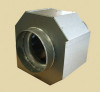
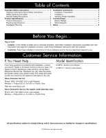
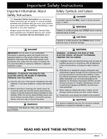
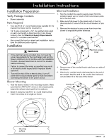
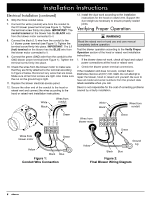
Installation Instructions Installation Preparation Verify Package Contents • Blower assembly Parts Required • Four (4) #10 X ¾", round head screws (suitable for the material the blower will be mounted to) • 1/2" 3 wire conduit with a 1/2" UL certified strain relief on each end (length is determined by in-line blower location). See the Electrical Supply Requirements section for complete specifications. • Also consult the hood or raised vent installation instructions for additional parts required. Installation Electrical Installation 1. Run the conduit line used to supply power from the installed raised vent or hood to the in-line blower parallel to the duct work. 2. Make sure that power to the raised vent or hood is disconnected or turned off at the circuit breaker or fuse box. 3. Remove the electrical access cover from the in-line blower to expose the power terminals. Knock-outs warning • If the electrical service provided does not meet the power requirements for the hood/raised vent and the blower combined, do not continue with the installation. Contact a licensed electrician to correct the situation before continuing. • Failure to connect the wiring as specified may result in an electric shock hazard and/or improper blower operation. • To avoid the risk of fire or electric shock, turn off power at the circuit breaker panel or fuse box before connecting the blower to the power source. Electrical access cover 4. Remove one of the conduit knock-outs from one side of the blower. 5. With the UL certified strain relief attached to the end of the conduit, feed the end of the conduit into the knock out and attach it to the side of the blower. Blower Mounting 1. Hold the blower steady in the mounting location. Make sure that the "AIR FLOW" arrow on the chassis points toward the exhaust duct's path to the outdoors. 2. Attach it using four (4) #10 X 2", round head screws. Insert the screws at an angle as shown. Knock-out BLK BLU GRN N1 L1 GND Conduit Blower Mounting surface 5
-
 1
1 -
 2
2 -
 3
3 -
 4
4 -
 5
5 -
 6
6 -
 7
7 -
 8
8 -
 9
9 -
 10
10 -
 11
11 -
 12
12
 |
 |