Dell 1600n Multifunction Mono Laser Printer Service Manual - Page 160
Printer - driver download
 |
View all Dell 1600n Multifunction Mono Laser Printer manuals
Add to My Manuals
Save this manual to your list of manuals |
Page 160 highlights
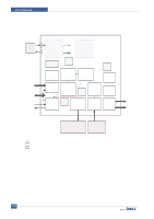
Circuit Diagram 11.4 Printer Section Printer is consisted of the Engine parts and F/W, and said engine parts is consisted of the mechanical parts comprising Frame, Feeding, Developing, Driving, Transferring, Fusing, Cabinet and H/W comprising the main control board, power board, operation panel, PC Interface. The main controller is consisted of Asic(SPGPm) parts, Memory parts, Engine interface parts and it functions as Bus Control, I/O Handing, drivers & PC Interface by CPU. Memory Access supports 16bit Operation, and Program Memory 2MB and Working Memory as well. The Engine Board and the Controller Board are in one united board, and it is consisted of CPU part and print part in functional aspect. The CPU is functioned as the bus control, I/O handling, drivers, and PC interface. The main board sends the Current Image, Video data to the LSU and manages the conduct of Electrophotography for printing. It is consisted of the circuits of the motor (paper feed, pass) driving, clutch driving, pre-transfer lamp driving, current driving, and fan driving. The signals from the paper feed jam sensor and paper empty sensor are directly inputted to the main board. 1) Printing Method: Laser-based Electrophotography 2) Supported Operating Systems: Windows 98/2000/NT4.0/ME/XP/ MAC (English only, no status monitor, web download only) 3) Emulation: SPL(GDI) , PCL6, PS3,PCL5e 4) Maximum Paper Size: Legal 5) Effective Printing Width: > Letter/Legal: 208mm > A4: 202mm 6) Resolution: > Addressable 1200 x1200 dpi (selectable from Print Driver) > 600x600 dpi (True; no RET) 7) Speed: 22ppm (Letter) 8) Input Paper Capacity: > Tray: 250 sheets (20 lb) > Bypass: Single sheet 9) Output Paper Capacity: 150 sheets (20 lb; sequenced 1 to N, face down) 10) Feed Direction: Front In, Front Out (FIFO) 11) PC Interface: > USB 2.0(without HUB mode) Requires 6 ft. USB Cable (not supplied by SEC) 12) Toner Cartridge: > Toner Low Sensor: None > Toner Low Indicator: Message displayed on LCD > Cartridge Missing Indicator: Message displayed on LCD 13) Paper Sensing: > Tray: "Add Paper" message displayed on LCD > Bypass: "Add Paper" message displayed on LCD 11-12 Service Manual
-
 1
1 -
2
-
3
-
4
-
5
-
6
-
7
-
8
-
9
-
10
-
11
-
12
-
13
-
14
-
15
-
16
-
17
-
18
-
19
-
20
-
21
-
22
-
23
-
24
-
25
-
26
-
27
-
28
-
29
-
30
-
31
-
32
-
33
-
34
-
35
-
36
-
37
-
38
-
39
-
40
-
41
-
42
-
43
-
44
-
45
-
46
-
47
-
48
-
49
-
50
-
51
-
52
-
53
-
54
-
55
-
56
-
57
-
58
-
59
-
60
-
61
-
62
-
63
-
64
-
65
-
66
-
67
-
68
-
69
-
70
-
71
-
72
-
73
-
74
-
75
-
76
-
77
-
78
-
79
-
80
-
81
-
82
-
83
-
84
-
85
-
86
-
87
-
88
-
89
-
90
-
91
-
92
-
93
-
94
-
95
-
96
-
97
-
98
-
99
-
100
-
101
-
102
-
103
-
104
-
105
-
106
-
107
-
108
-
109
-
110
-
111
-
112
-
113
-
114
-
115
-
116
-
117
-
118
-
119
-
120
-
121
-
122
-
123
-
124
-
125
-
126
-
127
-
128
-
129
-
130
-
131
-
132
-
133
-
134
-
135
-
136
-
137
-
138
-
139
-
140
-
141
-
142
-
143
-
144
-
145
-
146
-
147
-
148
-
149
-
150
-
151
-
152
-
153
-
154
-
 155
155 -
 156
156 -
 157
157 -
 158
158 -
 159
159 -
 160
160 -
 161
161 -
 162
162 -
 163
163 -
 164
164 -
 165
165 -
166
-
167
-
168
-
169
-
170
-
171
-
172
-
173
-
174
-
175
-
176
-
177
-
178
-
179
-
180
-
181
-
182
-
183
-
184
-
185
-
186
-
187
-
188
-
189
 |
 |
