| Section |
Page |
| Contents |
2 |
| Safety information |
12 |
| Learning about the printer |
14 |
| Printer configurations |
14 |
| Selecting a location for the printer |
14 |
| Basic functions of the scanner |
15 |
| Understanding the ADF and scanner glass |
16 |
| Understanding the printer control panel |
17 |
| Understanding the home screen |
18 |
| Using the touch-screen buttons |
20 |
| Additional printer setup |
24 |
| Installing internal options |
24 |
| Available internal options |
24 |
| Accessing the system board to install internal options |
25 |
| Installing a memory card |
27 |
| Installing a flash memory or firmware card |
28 |
| Installing an Internal Solutions Port |
31 |
| Installing a printer hard disk |
37 |
| Installing a fax card |
41 |
| Attaching cables |
43 |
| Verifying printer setup |
44 |
| Printing a menu settings page |
44 |
| Printing a network setup page |
45 |
| Setting up the printer software |
45 |
| Installing printer software |
45 |
| Updating available options in the printer driver |
46 |
| Setting up wireless printing |
47 |
| Information you will need to set up the printer on a wireless network |
47 |
| Installing the printer on a wireless network (Windows) |
47 |
| Installing the printer on a wireless network (Macintosh) |
49 |
| Installing the printer on a wired network |
52 |
| Changing port settings after installing a new network Internal Solutions Port |
55 |
| Setting up serial printing |
57 |
| Setting up the printer to fax |
59 |
| Choosing a fax connection |
59 |
| Using an RJ11 adapter |
60 |
| Connecting directly to a telephone wall jack in Germany |
63 |
| Connecting to a telephone |
64 |
| Connecting to an answering machine |
65 |
| Connecting to a computer with a modem |
67 |
| Setting the outgoing fax name and number |
68 |
| Setting the date and time |
68 |
| Turning Daylight Saving Time on |
69 |
| Loading paper and specialty media |
70 |
| Setting the Paper Size and Paper Type |
70 |
| Configuring Universal paper settings |
70 |
| Loading the standard or optional 250-sheet or 550-sheet tray |
71 |
| Loading the 2000-sheet tray |
74 |
| Loading the multipurpose feeder |
78 |
| Loading the envelope feeder |
80 |
| Linking and unlinking trays |
81 |
| Linking trays |
81 |
| Unlinking trays |
82 |
| Assigning a custom paper type name |
82 |
| Changing a Custom Type <x> name |
82 |
| Paper and specialty media guidelines |
84 |
| Paper guidelines |
84 |
| Paper characteristics |
84 |
| Unacceptable paper |
85 |
| Selecting paper |
85 |
| Selecting preprinted forms and letterhead |
85 |
| Using recycled paper and other office papers |
86 |
| Storing paper |
86 |
| Supported paper sizes, types, and weights |
87 |
| Paper sizes supported by the printer |
87 |
| Paper types and weights supported by the printer |
89 |
| Paper types and weights supported by the output bins |
89 |
| Copying |
91 |
| Making copies |
91 |
| Making a quick copy |
91 |
| Copying using the ADF |
91 |
| Copying using the scanner glass |
92 |
| Copying photos |
92 |
| Copying on specialty media |
92 |
| Making transparencies |
92 |
| Copying to letterhead |
93 |
| Customizing copy settings |
93 |
| Copying from one size to another |
93 |
| Making copies using paper from a selected tray |
94 |
| Copying a document that contains mixed paper sizes |
94 |
| Copying on both sides of the paper (duplexing) |
95 |
| Reducing or enlarging copies |
95 |
| Adjusting copy quality |
96 |
| Collating copies |
96 |
| Placing separator sheets between copies |
97 |
| Copying multiple pages onto a single sheet |
97 |
| Creating a custom job (job build) |
98 |
| Job interrupt |
99 |
| Placing information on copies |
99 |
| Placing the date and time at the top of each page |
99 |
| Placing an overlay message on each page |
99 |
| Canceling a copy job |
100 |
| Canceling a copy job while the document is in the ADF |
100 |
| Canceling a copy job while copying pages using the scanner glass |
100 |
| Canceling a copy job while the pages are being printed |
100 |
| Understanding the copy screens and options |
100 |
| Copy from |
100 |
| Copy to |
101 |
| Scale |
101 |
| Darkness |
101 |
| Content |
101 |
| Sides (Duplex) |
101 |
| Collate |
102 |
| Options |
102 |
| Improving copy quality |
103 |
| E-mailing |
104 |
| Getting ready to e-mail |
104 |
| Setting up the e-mail function |
104 |
| Configuring the e-mail settings |
105 |
| Creating an e-mail shortcut |
105 |
| Creating an e-mail shortcut using the Embedded Web Server |
105 |
| Creating an e-mail shortcut using the touch screen |
105 |
| E-mailing a document |
106 |
| Sending an e-mail using the touch screen |
106 |
| Sending an e-mail using a shortcut number |
106 |
| Sending an e-mail using the address book |
106 |
| Customizing e-mail settings |
107 |
| Adding e-mail subject and message information |
107 |
| Changing the output file type |
107 |
| Canceling an e-mail |
108 |
| Understanding e-mail options |
108 |
| Original Size |
108 |
| Sides (Duplex) |
108 |
| Orientation |
108 |
| Binding |
108 |
| E-mail Subject |
108 |
| E-mail File Name |
109 |
| E-mail Message |
109 |
| Resolution |
109 |
| Send As |
109 |
| Content |
109 |
| Advanced Options |
109 |
| Faxing |
111 |
| Sending a fax |
111 |
| Sending a fax using the printer control panel |
111 |
| Sending a fax using the computer |
112 |
| Creating shortcuts |
112 |
| Creating a fax destination shortcut using the Embedded Web Server |
112 |
| Creating a fax destination shortcut using the touch screen |
113 |
| Using shortcuts and the address book |
113 |
| Using fax shortcuts |
113 |
| Using the address book |
113 |
| Customizing fax settings |
114 |
| Changing the fax resolution |
114 |
| Making a fax lighter or darker |
114 |
| Sending a fax at a scheduled time |
115 |
| Viewing a fax log |
115 |
| Blocking junk faxes |
115 |
| Canceling an outgoing fax |
116 |
| Canceling a fax while the original documents are still scanning |
116 |
| Canceling a fax after the original documents have been scanned to memory |
116 |
| Understanding fax options |
116 |
| Original Size |
116 |
| Content |
117 |
| Sides (Duplex) |
117 |
| Resolution |
117 |
| Darkness |
117 |
| Advanced Options |
117 |
| Improving fax quality |
118 |
| Holding and forwarding faxes |
118 |
| Holding faxes |
118 |
| Forwarding a fax |
119 |
| Scanning to an FTP address |
120 |
| Scanning to an FTP address |
120 |
| Scanning to an FTP address using the keypad |
120 |
| Scanning to an FTP address using a shortcut number |
121 |
| Scanning to an FTP address using the address book |
121 |
| Creating shortcuts |
121 |
| Creating an FTP shortcut using the Embedded Web Server |
121 |
| Creating an FTP shortcut using the touch screen |
122 |
| Understanding FTP options |
122 |
| Original Size |
122 |
| Sides (Duplex) |
122 |
| Orientation |
122 |
| Binding |
122 |
| Resolution |
123 |
| Send As |
123 |
| Content |
123 |
| Advanced Options |
123 |
| Improving FTP quality |
124 |
| Scanning to a computer or flash drive |
125 |
| Scanning to a computer |
125 |
| Scanning to a flash drive |
126 |
| Understanding scan profile options |
126 |
| Quick Setup |
126 |
| Format Type |
127 |
| Compression |
127 |
| Default Content |
127 |
| Color |
127 |
| Original Size |
127 |
| Orientation |
127 |
| Sides (Duplex) |
127 |
| Darkness |
128 |
| Resolution |
128 |
| Advanced Imaging |
128 |
| Improving scan quality |
128 |
| Printing |
129 |
| Printing a document |
129 |
| Printing on specialty media |
129 |
| Tips on using letterhead |
129 |
| Tips on using transparencies |
130 |
| Tips on using envelopes |
130 |
| Tips on using labels |
131 |
| Tips on using card stock |
131 |
| Printing confidential and other held jobs |
132 |
| Holding jobs in the printer |
132 |
| Printing confidential and other held jobs from Windows |
132 |
| Printing confidential and other held jobs from a Macintosh computer |
133 |
| Printing from a flash drive |
134 |
| Printing information pages |
135 |
| Printing a directory list |
135 |
| Printing the print quality test pages |
135 |
| Canceling a print job |
135 |
| Canceling a print job from the printer control panel |
135 |
| Canceling a print job from the computer |
136 |
| Clearing jams |
138 |
| Avoiding jams |
138 |
| Understanding jam numbers and locations |
139 |
| 200 and 201 paper jams |
139 |
| 202 paper jam |
141 |
| 230–239 paper jams |
142 |
| 240–249 paper jams |
143 |
| 250 paper jam |
144 |
| 260 paper jam |
145 |
| 270–279 paper jams |
145 |
| 280–282 paper jams |
145 |
| 283 staple jams |
146 |
| 290–294 paper jams |
148 |
| Understanding printer menus |
150 |
| Menus list |
150 |
| Paper menu |
151 |
| Default Source menu |
151 |
| Paper Size/Type menu |
151 |
| Configure MP menu |
154 |
| Envelope Enhance |
155 |
| Substitute Size menu |
155 |
| Paper Texture menu |
155 |
| Paper Weight menu |
157 |
| Paper Loading menu |
158 |
| Custom Types menu |
159 |
| Custom Names menu |
160 |
| Custom Scan Sizes menu |
160 |
| Custom Bin Names menu |
160 |
| Universal Setup menu |
161 |
| Bin Setup menu |
161 |
| Reports menu |
162 |
| Network/Ports menu |
164 |
| Active NIC menu |
164 |
| Standard Network or Network <x> menus |
164 |
| SMTP Setup menu |
166 |
| Network Reports menu |
167 |
| Network Card menu |
167 |
| TCP/IP menu |
167 |
| IPv6 menu |
169 |
| Wireless menu |
169 |
| AppleTalk menu |
170 |
| NetWare menu |
170 |
| LexLink menu |
171 |
| Standard USB menu |
171 |
| Parallel <x> menu |
173 |
| Serial <x> menu |
175 |
| Security menu |
177 |
| Miscellaneous menu |
177 |
| Confidential Print menu |
178 |
| Disk Wiping menu |
179 |
| Security Audit Log menu |
180 |
| Set Date/Time menu |
181 |
| Settings menu |
181 |
| General Settings menu |
181 |
| Copy Settings menu |
189 |
| Fax Settings menu |
194 |
| E-mail Settings menu |
203 |
| FTP Settings menu |
208 |
| Flash Drive menu |
211 |
| Print Settings |
216 |
| Help menu |
228 |
| Understanding printer messages |
229 |
| List of status and error messages |
229 |
| Answering |
229 |
| Busy |
229 |
| Call complete |
229 |
| Change <src> to <x> |
229 |
| Check tray <x> connection |
229 |
| Close door or insert cartridge |
230 |
| Close finisher side door |
230 |
| Connect <x>bps |
230 |
| Dialing |
230 |
| Disk corrupted |
230 |
| Disk Full - Scan Job Canceled |
230 |
| Fax failed |
230 |
| Fax memory full |
231 |
| Fax partition inoperative. Contact system administrator. |
231 |
| Fax server 'To Format' not set up. Contact system administrator. |
231 |
| Fax Station Name not set up |
231 |
| Fax Station Number not set up |
231 |
| Flushing buffer |
231 |
| Insert staple cartridge |
231 |
| Insert Tray <x> |
232 |
| Install bin <x> |
232 |
| Install envelope feeder |
232 |
| Install Tray <x> |
232 |
| Invalid PIN |
232 |
| Job stored for delayed transmission |
233 |
| Line busy |
233 |
| Load <src> with <x> |
233 |
| Load manual feeder with <x> |
233 |
| Load staples |
233 |
| Memory full, cannot print faxes |
233 |
| Network/Network <x> |
233 |
| No analog phone line connected to modem, fax is disabled. |
234 |
| No answer |
234 |
| No dial tone |
234 |
| Queued for sending |
234 |
| Ready |
234 |
| Reattach bin <x> |
234 |
| Reattach bin <x> – <y> |
235 |
| Reattach envelope feeder |
235 |
| Receive complete |
235 |
| Receiving page <n> |
236 |
| Remove packaging material, check <x> |
236 |
| Remove paper from <linked bin set name> |
236 |
| Remove paper from all bins |
236 |
| Remove paper from bin <x> |
236 |
| Remove paper from standard output bin |
236 |
| Replace <x> if restarting job. |
236 |
| Replace wiper |
237 |
| Restore Held Jobs? |
237 |
| Scan Document Too Long |
237 |
| Scanner ADF Cover Open |
237 |
| Scanner Jam Access Cover Open |
237 |
| Securely clearing disk space |
237 |
| Sending page <n> |
237 |
| Serial <x> |
237 |
| Set clock |
237 |
| SMTP server not set up. Contact system administrator. |
237 |
| Some held jobs were not restored |
238 |
| System busy, preparing resources for job. |
238 |
| System busy, preparing resources for job. Deleting held job(s). |
238 |
| Unsupported disk |
238 |
| Unsupported USB device, please remove |
238 |
| Unsupported USB hub, please remove |
238 |
| USB/USB <x> |
238 |
| Waiting for redial |
238 |
| 30 Invalid refill, change cartridge |
238 |
| 31 Replace defective cartridge |
238 |
| 32 Cartridge part number unsupported by device |
238 |
| 34 Short paper |
239 |
| 35 Insufficient memory to support Resource Save feature |
239 |
| 37 Insufficient memory to collate job |
239 |
| 37 Insufficient memory for Flash Memory Defragment operation |
239 |
| 37 Insufficient memory, some Held Jobs were deleted |
239 |
| 37 Insufficient memory, some held jobs will not be restored |
239 |
| 38 Memory full |
240 |
| 39 Complex page, some data may not have printed |
240 |
| 42.xy Cartridge region mismatch |
240 |
| 50 PPDS font error |
240 |
| 51 Defective flash detected |
240 |
| 52 Not enough free space in flash memory for resources |
241 |
| 53 Unformatted flash detected |
241 |
| 54 Network <x> software error |
241 |
| 54 Serial option <x> error |
241 |
| 54 Standard network software error |
241 |
| 55 Unsupported option in slot <x> |
242 |
| 56 Parallel port <x> disabled |
242 |
| 56 Serial port <x> disabled |
242 |
| 56 Standard parallel port disabled |
242 |
| 56 Standard USB port disabled |
242 |
| 56 USB port <x> disabled |
243 |
| 57 Configuration change, held jobs were not restored |
243 |
| 58 Too many bins attached |
243 |
| 58 Too many disks installed |
243 |
| 58 Too many flash options installed |
243 |
| 58 Too many trays attached |
244 |
| 59 Incompatible envelope feeder |
244 |
| 59 Incompatible output bin <x> |
244 |
| 59 Incompatible tray <x> |
244 |
| 61 Remove defective disk |
244 |
| 62 Disk full |
244 |
| 63 Unformatted disk |
245 |
| 80 Routine maintenance needed |
245 |
| 88 Cartridge low |
245 |
| 88.yy Cartridge nearly low |
245 |
| 88.yy Replace cartridge |
245 |
| 200–282.yy paper jam |
245 |
| 283 Staple jam |
245 |
| 290-294.yy scanner jam |
245 |
| 293 Replace all originals if restarting job. |
245 |
| 293.02 Flatbed Cover Open |
246 |
| 840.01 Scanner Disabled |
246 |
| 841-846 Scanner Service Error |
246 |
| 900–999 Service <message> |
246 |
| 1565 Emulation error, load emulation option |
247 |
| Maintaining the printer |
248 |
| Cleaning the exterior of the printer |
248 |
| Cleaning the scanner glass |
248 |
| Adjusting scanner registration |
249 |
| Storing supplies |
250 |
| Conserving supplies |
251 |
| Checking the status of supplies |
251 |
| Checking the status of supplies from the printer control panel |
251 |
| Checking the status of supplies from a network computer |
251 |
| Ordering supplies |
252 |
| Ordering print cartridges |
252 |
| Moving the printer |
252 |
| Before moving the printer |
252 |
| Moving the printer to another location |
253 |
| Setting the printer up in a new location |
253 |
| Shipping the printer |
253 |
| Administrative support |
254 |
| Using the Embedded Web Server |
254 |
| Checking the device status |
254 |
| Setting up e-mail alerts |
254 |
| Viewing reports |
255 |
| Adjusting the brightness of the display |
255 |
| Adjusting Power Saver |
255 |
| Restoring the factory default settings |
256 |
| Troubleshooting |
257 |
| Solving basic printer problems |
257 |
| Printer control panel display is blank or displays only diamonds |
257 |
| Solving printing problems |
257 |
| Multiple-language PDFs do not print |
257 |
| Error message about reading USB drive appears |
257 |
| Jobs do not print |
258 |
| Confidential and other held jobs do not print |
258 |
| Job takes longer than expected to print |
259 |
| Job prints from the wrong tray or on the wrong paper |
259 |
| Incorrect characters print |
259 |
| Tray linking does not work |
260 |
| Large jobs do not collate |
260 |
| Unexpected page breaks occur |
260 |
| Solving copy problems |
261 |
| Copier does not respond |
261 |
| Scanner unit does not close |
261 |
| Poor copy quality |
261 |
| Partial document or photo copies |
263 |
| Solving scanner problems |
263 |
| Checking an unresponsive scanner |
263 |
| Scan was not successful |
263 |
| Scanning takes too long or freezes the computer |
264 |
| Poor scanned image quality |
264 |
| Partial document or photo scans |
264 |
| Cannot scan from a computer |
265 |
| Solving fax problems |
265 |
| Caller ID is not shown |
265 |
| Cannot send or receive a fax |
265 |
| Can send but not receive faxes |
267 |
| Can receive but not send faxes |
268 |
| Received fax has poor print quality |
268 |
| Solving option problems |
269 |
| Option does not operate correctly or quits after it is installed |
269 |
| Paper trays |
269 |
| 2000-sheet tray |
270 |
| Envelope feeder |
270 |
| Output options |
271 |
| Flash memory card |
271 |
| Hard disk with adapter |
271 |
| Internal Solutions Port |
271 |
| Memory card |
271 |
| Solving paper feed problems |
272 |
| Paper frequently jams |
272 |
| Paper jam message remains after jam is cleared |
272 |
| Page that jammed does not reprint after you clear the jam |
272 |
| Solving print quality problems |
273 |
| Isolating print quality problems |
273 |
| Blank pages |
273 |
| Characters have jagged or uneven edges |
274 |
| Clipped images |
274 |
| Ghost images |
274 |
| Gray background |
275 |
| Incorrect margins |
275 |
| Paper curl |
276 |
| Print irregularities |
276 |
| Repeating defects |
277 |
| Skewed print |
278 |
| Solid black or white streaks |
278 |
| Print is too light |
279 |
| Print is too dark |
280 |
| Solid color pages |
281 |
| Streaked vertical lines |
281 |
| Toner fog or background shading appears on the page |
282 |
| Toner rubs off |
282 |
| Toner specks |
283 |
| Transparency print quality is poor |
283 |
| Embedded Web Server does not open |
283 |
| Check the network connections |
283 |
| Check the network settings |
284 |
| Contacting Customer Support |
284 |
| Notices |
285 |
| Edition notice |
285 |
| UNITED STATES GOVERNMENT RIGHTS |
285 |
| Federal Communications Commission (FCC) compliance information statement |
285 |
| Compliance statement |
286 |
| Exposure to radio frequency radiation |
286 |
| Industry Canada notices |
286 |
| Industry Canada radio interference statement |
286 |
| Radio interference notice |
287 |
| European Community (EC) directives conformity |
287 |
| India emissions notice |
289 |
| Noise emission levels |
289 |
| Temperature information |
289 |
| Product disposal |
289 |
| Federal Communications Commission (FCC) compliance information statement |
290 |
| Notice to users of the Canadian telephone network |
291 |
| Notice to users of the New Zealand telephone network |
291 |
| South Africa telecommunications notice |
292 |
| ENERGY STAR |
293 |
| Laser notice |
293 |
| Laser advisory label |
293 |
| Power consumption |
293 |
| Product power consumption |
293 |
| Power Saver |
294 |
| Off mode |
294 |
| Total energy usage |
294 |
 1
1 29
29 30
30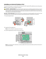 31
31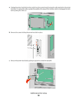 32
32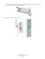 33
33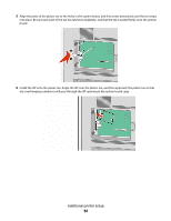 34
34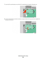 35
35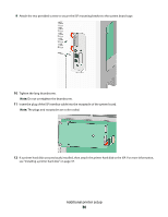 36
36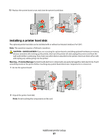 37
37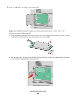 38
38 39
39