Dell Alienware Area-51 Threadripper Edition R3 Alienware Area-51 Threadripper - Page 51
Replacing the right AlienFX side-panel connector, Procedure, Post-requisites
 |
View all Dell Alienware Area-51 Threadripper Edition R3 manuals
Add to My Manuals
Save this manual to your list of manuals |
Page 51 highlights
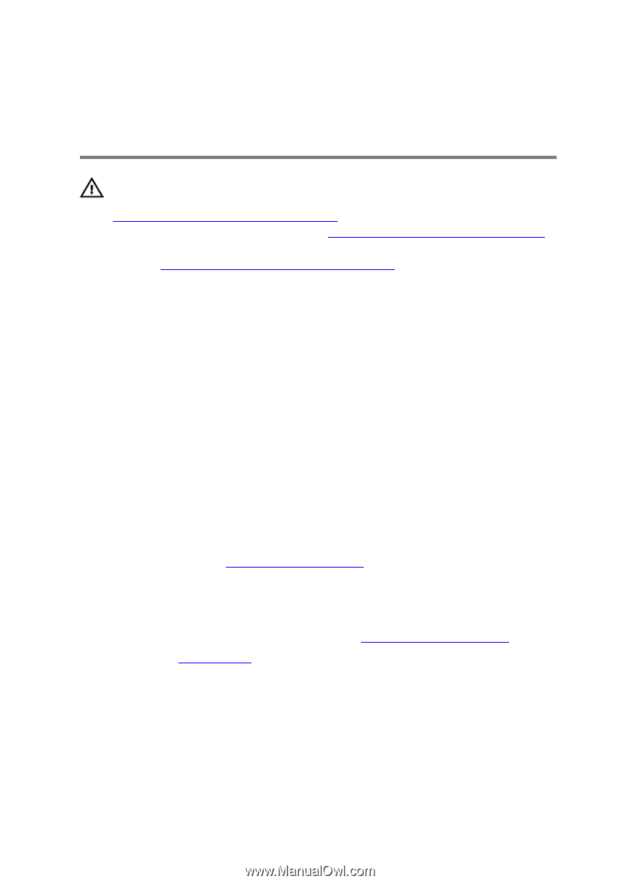
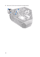
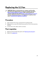
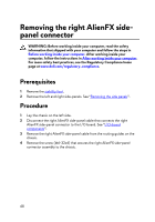
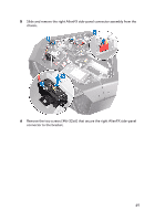
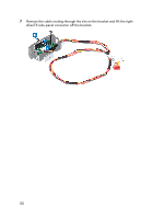
Replacing the right AlienFX sidepanel connector WARNING: Before working inside your computer, read the safety information that shipped with your computer and follow the steps in Before working inside your computer. After working inside your computer, follow the instructions in After working inside your computer. For more safety best practices, see the Regulatory Compliance home page at www.dell.com/regulatory_compliance. Procedure 1 Route the cable through the slot on the bracket and align the screw holes on the right AlienFX side-panel connector with the screw holes on the bracket. 2 Replace the two screws (#6-32x6) that secure the right AlienFX side-panel connector to the bracket. 3 Align the screw hole on the right AlienFX side-panel connector assembly with the screw hole on the chassis. 4 Replace the screw (#6-32x6) that secures the right AlienFX side-panel connector assembly to the chassis. 5 Route the right AlienFX side-panel cable through the routing guides on the chassis. 6 Connect the cable that connects the right AlienFX side-panel connector to the I/O board. See "I/O-board components". Post-requisites 1 Replace the left and right side-panels. See "Replacing the side panels". 2 Replace the stability foot. 51
-
 1
1 -
2
-
3
-
4
-
5
-
6
-
7
-
8
-
9
-
10
-
11
-
12
-
13
-
14
-
15
-
16
-
17
-
18
-
19
-
20
-
21
-
22
-
23
-
24
-
25
-
26
-
27
-
28
-
29
-
30
-
31
-
32
-
33
-
34
-
35
-
36
-
37
-
38
-
39
-
40
-
41
-
42
-
43
-
44
-
45
-
 46
46 -
 47
47 -
 48
48 -
 49
49 -
 50
50 -
 51
51 -
 52
52 -
 53
53 -
 54
54 -
 55
55 -
 56
56 -
57
-
58
-
59
-
60
-
61
-
62
-
63
-
64
-
65
-
66
-
67
-
68
-
69
-
70
-
71
-
72
-
73
-
74
-
75
-
76
-
77
-
78
-
79
-
80
-
81
-
82
-
83
-
84
-
85
-
86
-
87
-
88
-
89
-
90
-
91
-
92
-
93
-
94
-
95
-
96
-
97
-
98
-
99
-
100
-
101
-
102
-
103
-
104
-
105
-
106
-
107
-
108
-
109
-
110
-
111
-
112
-
113
-
114
-
115
-
116
-
117
-
118
-
119
-
120
-
121
-
122
-
123
-
124
-
125
-
126
-
127
-
128
-
129
-
130
-
131
-
132
-
133
-
134
-
135
-
136
-
137
-
138
-
139
-
140
-
141
-
142
-
143
-
144
-
145
-
146
-
147
-
148
-
149
-
150
-
151
-
152
-
153
-
154
-
155
-
156
-
157
-
158
-
159
-
160
-
161
-
162
-
163
-
164
-
165
-
166
-
167
-
168
-
169
-
170
-
171
-
172
-
173
-
174
-
175
-
176
-
177
-
178
-
179
 |
 |