Dell Alienware M14x R2 Owner's Manual - Page 93
Replacing the Processor Module
 |
View all Dell Alienware M14x R2 manuals
Add to My Manuals
Save this manual to your list of manuals |
Page 93 highlights
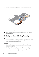
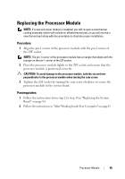
Replacing the Processor Module NOTE: If a new processor module is installed, you will receive a new thermal cooling assembly, which will include an affixed thermal pad, or you will receive a new thermal pad along with documentation to illustrate proper installation. Procedure 1 Align the pin-1 corner of the processor module with the pin-1 corner of the ZIF socket. NOTE: The pin-1 corner of the processor module has a triangle that aligns with the triangle on the pin-1 corner of the ZIF socket. 2 Place the processor module lightly in the ZIF socket and ensure that the processor module is positioned correctly. CAUTION: To avoid damage to the processor module, hold the screwdriver perpendicular to the processor module when turning the cam screw. 3 Tighten the ZIF socket by turning the cam screw clockwise to secure the processor module to the system board. Postrequisites 1 Follow the instructions from step 2 to step 18 in "Replacing the System Board" on page 84. 2 Follow the instructions in "After Working Inside Your Computer" on page13. Processor Module 95
-
 1
1 -
2
-
3
-
4
-
5
-
6
-
7
-
8
-
9
-
10
-
11
-
12
-
13
-
14
-
15
-
16
-
17
-
18
-
19
-
20
-
21
-
22
-
23
-
24
-
25
-
26
-
27
-
28
-
29
-
30
-
31
-
32
-
33
-
34
-
35
-
36
-
37
-
38
-
39
-
40
-
41
-
42
-
43
-
44
-
45
-
46
-
47
-
48
-
49
-
50
-
51
-
52
-
53
-
54
-
55
-
56
-
57
-
58
-
59
-
60
-
61
-
62
-
63
-
64
-
65
-
66
-
67
-
68
-
69
-
70
-
71
-
72
-
73
-
74
-
75
-
76
-
77
-
78
-
79
-
80
-
81
-
82
-
83
-
84
-
85
-
86
-
87
-
 88
88 -
 89
89 -
 90
90 -
 91
91 -
 92
92 -
 93
93 -
 94
94 -
 95
95 -
 96
96 -
 97
97 -
 98
98 -
99
-
100
-
101
-
102
-
103
-
104
 |
 |
