Dell DAE2P Hardware Reference - Page 27
Drive carrier, Power supply/system cooling modules
 |
View all Dell DAE2P manuals
Add to My Manuals
Save this manual to your list of manuals |
Page 27 highlights
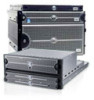
About DAE2P and DAE3P disk enclosures Drive modules are extremely sensitive electronic components. Refer to the instructions on "Handling FRUs" whenever you handle a disk module. Drive carrier The disk drive carriers are metal and plastic assemblies that provide smooth, reliable contact with the enclosure slot guides and midplane connectors. Each carrier has a handle with a latch and spring clips. The latch holds the disk module in place to ensure proper connection with the midplane. Disk drive Activity/Fault LEDs are integrated into the carrier. Power supply/system cooling modules The power supply/system cooling (power/cooling) modules are located above and below the LCCs. The units integrate independent power supply and dual-blower cooling assemblies into a single module. Each power supply is an auto-ranging, power-factor-corrected, multi-output, off-line converter with its own line cord. Each supply supports a fully configured DAE2P/DAE3P and shares load currents with the other supply. The drives and LCC have individual soft-start switches that protect the disk drives and LCCs if you install them while the disk enclosure is powered up. A FRU (disk, LCC, or power/cooling module) with power-related faults will not adversely affect the operation of any other FRU. The enclosure cooling system includes two dual-blower modules. If one blower fails, the others will speed up to compensate. If two blowers in a system (both in one power/cooling module, or one in each module) fail, the DAE2P/DAE3P will go off line within two minutes. Each power/cooling module has three visible status lights. The green LED indicates power to the supply; the center LED indicates a power supply fault. The remaining LED indicates a failure in one of the integrated blowers within that module. The status lights are shown in Figure 1-9 and described in "Monitoring disk enclosure status" in Chapter 3. Power supply/system cooling modules 1-11
-
 1
1 -
2
-
3
-
4
-
5
-
6
-
7
-
8
-
9
-
10
-
11
-
12
-
13
-
14
-
15
-
16
-
17
-
18
-
19
-
20
-
21
-
 22
22 -
 23
23 -
 24
24 -
 25
25 -
 26
26 -
 27
27 -
 28
28 -
 29
29 -
 30
30 -
 31
31 -
 32
32 -
33
-
34
-
35
-
36
-
37
-
38
-
39
-
40
-
41
-
42
-
43
-
44
-
45
-
46
-
47
-
48
-
49
-
50
-
51
-
52
-
53
-
54
-
55
-
56
-
57
-
58
-
59
-
60
-
61
-
62
-
63
-
64
-
65
-
66
-
67
-
68
-
69
-
70
-
71
-
72
-
73
-
74
-
75
-
76
 |
 |
