Dell EqualLogic PS6210E PS6210 Hardware Owners Manual - Page 23
Control Module LEDs, Table 6: Ethernet and Management Port LED Descriptions
 |
View all Dell EqualLogic PS6210E manuals
Add to My Manuals
Save this manual to your list of manuals |
Page 23 highlights
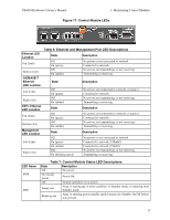
PS6210 Hardware Owner's Manual 3 Maintaining Control Modules Figure 17: Control Module LEDs Ethernet LED Location Top (Link) Bottom (Act) 10GBASE-T Ethernet LED Location Left (Link) Right (Act) SPF+ Ethernet LED Location Top (Link) Bottom (Act) Management LED Location Left (Link) Right (Act) Table 6: Ethernet and Management Port LED Descriptions State Description Off On (green) Off On (amber) No power or not connected to network. Connected to network. No power, not transmitting, or not receiving. Transmitting or receiving. State Description Off On (green) Off On (amber) State Off On (green) Off On (amber) State Off On (green) On (amber) Off On (blinking green) No power, not connected to network, or passive. Connected to network. No power, not transmitting, or not receiving. Transmitting or receiving. Description No power, not connected to network, or passive. Connected to network. No power, not transmitting, or not receiving. Transmitting or receiving. Description No power or not connected to network. Connected to network (100mbit). Connected to network (10mbit). No power, not transmitting, or not receiving. Transmitting or receiving. LED Name PWR ERR Table 7: Control Module Status LED Descriptions State Description Off No power. On (steady green) Power/OK. Off Normal operation or no power. Steady red Array is starting up, in error condition, in Standby mode, or returning from Standby mode. Blinking red Array is entering power standby mode because the Standby On/Off button was pressed. 17
-
 1
1 -
2
-
3
-
4
-
5
-
6
-
7
-
8
-
9
-
10
-
11
-
12
-
13
-
14
-
15
-
16
-
17
-
 18
18 -
 19
19 -
 20
20 -
 21
21 -
 22
22 -
 23
23 -
 24
24 -
 25
25 -
 26
26 -
 27
27 -
 28
28 -
29
-
30
-
31
-
32
-
33
-
34
-
35
-
36
-
37
-
38
-
39
-
40
-
41
-
42
-
43
-
44
-
45
-
46
-
47
-
48
 |
 |
