Dell EqualLogic PS6210XS PS6210 Installation and Setup Guide - Page 23
Serial Cable Pinout Information, Connecting a Serial Cable to the Array 4U Array
 |
View all Dell EqualLogic PS6210XS manuals
Add to My Manuals
Save this manual to your list of manuals |
Page 23 highlights
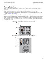
PS6210 Install and Setup Guide 3 Connecting the Array Cables Figure 10: Connecting a Serial Cable to the Array (4U Array) Serial Cable Pinout Information Figure 11 shows the pin locations on the DB9 connectors on the serial cable shipped with the array, and Table 5 lists the pinout information for the cable. Figure 11: Serial Cable DB9 Connector - Pin Locations Table 5: DB9 to DB9 Pinout Information DB9-1 DB9-2 Function Pin Pin Function Receive Data 2 3 Transmit Data Transmit Data 3 2 Receive Data Data Terminal Ready 4 6+1 Data Set Ready + Carrier Detect System Ground 5 5 System Ground Data Set Ready + Carrier Detect 6+1 4 Data Terminal Ready Request to Send 7 8 Clear to Send Clear to Send 8 7 Request to Send 15
-
 1
1 -
2
-
3
-
4
-
5
-
6
-
7
-
8
-
9
-
10
-
11
-
12
-
13
-
14
-
15
-
16
-
17
-
 18
18 -
 19
19 -
 20
20 -
 21
21 -
 22
22 -
 23
23 -
 24
24 -
 25
25 -
 26
26 -
 27
27 -
 28
28 -
29
-
30
-
31
-
32
-
33
-
34
-
35
-
36
-
37
-
38
-
39
-
40
-
41
-
42
-
43
-
44
-
45
-
46
 |
 |

PS6210 Install and Setup Guide
3 Connecting the Array Cables
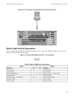
Figure 10: Connecting a Serial Cable to the Array (4U Array)
Serial Cable Pinout Information
Figure 11
shows the pin locations on the DB9 connectors on the serial cable shipped with the array, and
Table 5
lists the pinout information for the cable.
Figure 11: Serial Cable DB9 Connector - Pin Locations
Table 5: DB9 to DB9 Pinout Information
DB9-1
DB9-2
Function
Pin
Pin
Function
Receive Data
2
3
Transmit Data
Transmit Data
3
2
Receive Data
Data Terminal Ready
4
6+1
Data Set Ready + Carrier Detect
System Ground
5
5
System Ground
Data Set Ready + Carrier Detect
6+1
4
Data Terminal Ready
Request to Send
7
8
Clear to Send
Clear to Send
8
7
Request to Send
15