Dell External OEMR R410 Technical Guide - Page 20
Opening and Closing the System, Removing and Replacing the Optional Front Bezel, Hard Drives - certification
 |
View all Dell External OEMR R410 manuals
Add to My Manuals
Save this manual to your list of manuals |
Page 20 highlights
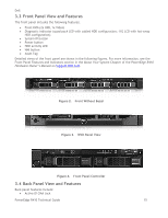
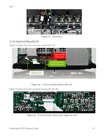
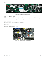
Dell Security 3.10.1 Cover Latch The PowerEdge R410 comes with a coin lock entry latch on the top cover of the unit and provides security for the entire system. Also, the lock provides for toolless access to the chassis. For specific information regarding the opening and closing of the system, see the Opening and Closing the System section in the Installing System Components chapter of the PowerEdge R410 Hardware Owner's Manual. 3.10.2 Bezel A metal bezel is an available option and is mounted to the chassis front to provide the Dell ID. A lock on the bezel prevents un-authorized access to system peripherals and the control panel. System status (via the LCD) remains viewable with the bezel is installed. For specific instructions regarding the operation of the bezel, see the Removing and Replacing the Optional Front Bezel in the Installing System Components chapter of the PowerEdge R410 Hardware Owner's Manual. 3.10.3 Hard Drive Hot-Plug Hard drives are only accessible by opening the bezel, thus locking the bezel secures the hard drives. Cabled Hard drives are only accessible by opening the top cover, thus locking the top cover will secure the hard drives. See the Hard Drives section in the Installing System Components chapter of the PowerEdge R410 Hardware Owner's Manual for information. 3.10.4 Trusted Platform Management (TPM) The TPM is used to generate/store keys, protect/authenticate passwords, and create/store digital certificates. TPM can also be used to store the BitLocker keys for hard drive encryption feature in Microsoft® Windows Server® 2008. TPM is enabled through a BIOS option and uses HMAC-SHA1-160 for binding. In China, S-TPM (Socket TPM) is used. 3.10.5 Power-Off Security The control panel is designed so that the power switch cannot be accidentally activated. The lock on the bezel secures the switch behind the bezel. In addition, a setting in the CMOS setup disables the power button function. 3.10.6 Intrusion Alert Chassis intrusion switch is located on the front panel board as shown in Figure 14. The switch detects when the top cover is opened. PowerEdge R410 Technical Guide 20
-
 1
1 -
2
-
3
-
4
-
5
-
6
-
7
-
8
-
9
-
10
-
11
-
12
-
13
-
14
-
 15
15 -
 16
16 -
 17
17 -
 18
18 -
 19
19 -
 20
20 -
 21
21 -
 22
22 -
 23
23 -
 24
24 -
 25
25 -
26
-
27
-
28
-
29
-
30
-
31
-
32
-
33
-
34
-
35
-
36
-
37
-
38
-
39
-
40
-
41
-
42
-
43
-
44
-
45
-
46
-
47
-
48
-
49
-
50
-
51
-
52
-
53
-
54
-
55
-
56
-
57
-
58
 |
 |
