Dell Force10 S25N-S50N Installing S50N and S50V Systems - Page 12
Table 2-2., Status Panel LED Display
 |
View all Dell Force10 S25N-S50N manuals
Add to My Manuals
Save this manual to your list of manuals |
Page 12 highlights
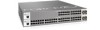
www.dell.com | support.dell.com NOTE: As suggested by the footnote above, the fiber SFP ports have priority over the four 10/100/1000 ports with the same number. The following table describes the LED status indicators on the left side of the front panel. Table 2-2. Status Panel LED Display Label LED Color Left Side of the Status Panel OK Green Off Green Blinking Amber AC (on the S50V and S50N) DC1 (on the S50N-DC) Green Amber Off XFP49* Green Blinking Green Off XFP50* Green Blinking Green Off STACK ID Green Right Side of the Status Panel Alarm Amber Red Off DC (on the S50V and S50N) DC2 (on the S50N-DC) Green Amber Off XFP51* Green Blinking Green Off XFP52* Green Blinking Green Off Description Unit is online. Unit is powered off. Unit is booting up. (blinking rate is 16 Hz) Error during boot-up. Power supply is present and OK. Power supply is present but failed. Power supply is not present. A valid 10G link is established on the port. Transmitting or receiving packets on the port. No link is established on the port. A valid 10G link is established on the port. Transmitting or receiving packets on the port. No link is established on the port. Indicates the stack ID (sometimes called "switch ID") of the unit. Starting with FTOS 7.8.1.0: • "A" is displayed to the left of the stack ID if the unit is a standalone or master (management) unit. • "B" is displayed for a standby unit. (Actually, it's an 8, because of the limitations of the 7-segment LED.) • "0" is displayed next to the stack ID, as before, for the other units. Minor alarm: Fan or temperature is operating outside parameters. Major alarm No alarm Power supply is present and OK. Power supply is present but failed. Power supply is not present. A valid 10G link is established on the port. Transmitting or receiving packets on the port. No link is established on the port. A valid 10G link is established on the port. Transmitting or receiving packets on the port. No link is established on the port. *The four XFP LEDs on the front panel also indicate the status when CX4 ports are installed in the bay. 12 | System Overview
-
 1
1 -
2
-
3
-
4
-
5
-
6
-
 7
7 -
 8
8 -
 9
9 -
 10
10 -
 11
11 -
 12
12 -
 13
13 -
 14
14 -
 15
15 -
 16
16 -
 17
17 -
18
-
19
-
20
-
21
-
22
-
23
-
24
-
25
-
26
-
27
-
28
-
29
-
30
-
31
-
32
-
33
-
34
-
35
-
36
-
37
-
38
-
39
-
40
-
41
-
42
-
43
-
44
-
45
-
46
-
47
-
48
-
49
-
50
-
51
-
52
-
53
-
54
-
55
-
56
-
57
-
58
-
59
-
60
-
61
-
62
-
63
-
64
 |
 |
