Dell Force10 S60-44T Installing the S60 System
Dell Force10 S60-44T Manual
 |
View all Dell Force10 S60-44T manuals
Add to My Manuals
Save this manual to your list of manuals |
Dell Force10 S60-44T manual content summary:
- Dell Force10 S60-44T | Installing the S60 System - Page 1
Installing the S60 System Publication Date: March 2012 - Dell Force10 S60-44T | Installing the S60 System - Page 2
or loss of data if you do not follow the instructions. WARNING: A WARNING indicates a potential for property damage, personal injury, or death. Information in this publication is subject to change without notice. © 2012 Dell Force10. All rights reserved. Reproduction of these materials in any manner - Dell Force10 S60-44T | Installing the S60 System - Page 3
Stacking Ports (Optional 18 Important Points to Know 18 Connect Two S60 Systems 19 Connect Three or More S60 Systems 20 Supply Power and Power Up the System 22 Power Up Sequence 23 AC Power 23 DC Power 23 Hot-swap Units in a Stack 24 4 Power Supplies Components 27 Install an AC or DC - Dell Force10 S60-44T | Installing the S60 System - Page 4
www.dell.com | support.dell.com 6 Access the Console Ports Access the RJ-45 Console Port (RS-232 35 Access the RJ-45 Console Port with a DB-9 Adapter 36 Access the USB-B Console Port 36 7 S60 Specifications Chassis Physical Design 39 Environmental Parameters 39 AC Power Requirements 39 DC - Dell Force10 S60-44T | Installing the S60 System - Page 5
-up of the S60 system, for software configuration information, refer to the FTOS Configuration Guide for the S60 System and for Command Line Interface (CLI) information, refer to the FTOS Command Line Reference Guide for the S60 System. NOTE: The S60 system requires Dell Force10 Operating Software - Dell Force10 S60-44T | Installing the S60 System - Page 6
www.dell.com | support.dell.com Related Publications For more information about the S60 system, refer to the following documents: • FTOS Configuration Guide for the S60 System • FTOS Command Line Reference Guide for the S60 System • FTOS Release Notes for the S60 System NOTE: For the most recent - Dell Force10 S60-44T | Installing the S60 System - Page 7
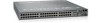
Force10 S60 system is a high-performance, high-capacity, low-cost, stackable, Layer 2 switch/ Layer 3 router that supports 44 built-in 10/100/1000 Base-T ports, four Small Form-Factor Pluggable (SFP) ports, an optional Small Form-Factor Pluggable Plus (SFP+) module, and optional 12G or 24G stacking - Dell Force10 S60-44T | Installing the S60 System - Page 8
S60-PWR-AC S60 AC PSU with 1 reverse-flow fan module S60-PWR-AC-R S60 DC PSU with 1 fan module S60-PWR-DC S60 DC PSU with 1 reverse-flow fan module S60-PWR-DC-R S60 fan filter S60-PWR-FLTR S60 fan filter for NEBS compliance S60-PWR-FLTR-NEBS S60 2-port, 12 Gigabit stacking module S60-12G - Dell Force10 S60-44T | Installing the S60 System - Page 9
or 1000 Base-X using auto-media detection • Optional ports supporting one 2-port, 24G stacking module or two 1-port, 12G stacking modules • Console port • Universal Serial Bus (USB)-A port • USB-B port System Status You can view S60 status information in several ways, including physical displays and - Dell Force10 S60-44T | Installing the S60 System - Page 10
to the first release of the S60 system. Figure 2-3. Stack ID Hexidecimal Display • The stack master indicator displays: • Stack Master-decimal LED ON • Stack standby-decimal LED blinking • Member-decimal LED Off • Below the Stack ID LED and above the optional module ports are four LEDs that display - Dell Force10 S60-44T | Installing the S60 System - Page 11
In addition to the system LEDs, each port has status indicator LEDs. Table 2-2 lists the port LED displays. Table 2-2. Port LED Displays Feature 10/100/1000 Port LEDs SFP+ Port LED Stacking Module LEDs Description • Link LED (on the left side of each port): Green-1000M Yellow-10/100M Off-No link • - Dell Force10 S60-44T | Installing the S60 System - Page 12
12 | The S60 System www.dell.com | support.dell.com - Dell Force10 S60-44T | Installing the S60 System - Page 13
describes the installation procedures as follows: 1 Install the S60 System in a Rack or Cabinet a Attach the Mounting Brackets b Install the Chassis into the Rack or Cabinet 2 Attach the Ground Cable 3 Insert Optional Modules 4 Connect Stacking Ports (Optional) 5 Supply Power and Power Up the System - Dell Force10 S60-44T | Installing the S60 System - Page 14
www.dell.com | support.dell.com To attach the brackets to the chassis, follow these steps: is adequate clearance surrounding the rack or within the cabinet. If you are installing two S60 switches side-by-side, to permit proper airflow, position the two chassis at least five inches (12.7 cm - Dell Force10 S60-44T | Installing the S60 System - Page 15
To install a switch into a two-post 19-inch equipment rack, using the already attached mounting brackets, follow these steps: Step 1 Task NOTE: Dell Force10 recommends one person holding the S60 chassis in place while another person attaches the brackets to the posts. Attach the bracket "ears" to - Dell Force10 S60-44T | Installing the S60 System - Page 16
www.dell.com | support.dell.com Step Task ( module, the interfaces and their configurations are removed as well. Table 3-1. Optional Modules Module Description 2-port, 12G stacking module Catalog Number S60-12G-2ST 1-port, 24G stacking module S60-24G-1ST 2-port, 10G SFP+ optical module S60 - Dell Force10 S60-44T | Installing the S60 System - Page 17
module. Install the SFP and SFP+ Optics In addition to the optional SFP+ optical modules, the S60 system has four Small Form-Factor Pluggable (SFP) optical ports in optic into the port until it gently snaps into place. NOTE: For more information about Dell Force10 supported optics, refer to - Dell Force10 S60-44T | Installing the S60 System - Page 18
Dell Force10 recommends using the ring topology. Figure 3-1. S60 Stacking Topology with 2-port, 12G Stacking Modules Ring Topology (with 2-port 12G modules) Cascade Topology (with 2-port 12G modules) Switch 1 48 49 48 49 Switch 1 Switch 2 48 49 48 49 Switch 2 Switch 3 48 49 48 49 Switch - Dell Force10 S60-44T | Installing the S60 System - Page 19
and insert the other end into a stacking port of the adjacent switch. To ensure the cable is secure in the connector, hand-tighten all the captive screws. Connect Two S60 Systems 2-port, 12G Stacking Modules As an option, when using the 2-port, 12G stacking modules, insert a second cable into the - Dell Force10 S60-44T | Installing the S60 System - Page 20
dell.com | support.dell.com Figure 3-3. Two S60 Systems with 2-port, 12G Stacking Modules Connected in a Ring Topology 1-port, 24G stacking modules The 1-port, 24G stacking module requires the S60 systems be cabled across the front-ports-to-rear-port, or vice versa (Figure 3-4). To connect 1-port - Dell Force10 S60-44T | Installing the S60 System - Page 21
To connect 2-port, 12G stacking modules, starting with the S60 system at the bottom of the stack, follow these steps: Step Task 1 Insert one end of the first cable into Stack Port 48 (or 50). 2 Insert the other end of the cable into Stack Port 48 (or 50) of the middle S60 system. 3 Insert - Dell Force10 S60-44T | Installing the S60 System - Page 22
www.dell.com | support.dell.com 1-port, 24G Stacking Modules The 1-port, 24G stacking module requires the S60 systems be cabled from the front-ports-to-rear-port, or vice versa (Figure 3-6). To connect 1-port, 24G stacking modules, starting with the S60 system at the bottom of the stack, follow - Dell Force10 S60-44T | Installing the S60 System - Page 23
you did not install optional modules. NOTE: A US AC power cable is included in the shipping container for powering up an AC PSU. You must order all the S60 system and the power source, the system is powered-up; there is no on/off switch. Figure 3-7. AC Power Connection DC Power To connect DC power - Dell Force10 S60-44T | Installing the S60 System - Page 24
dell.com | support.dell.com Step 4 Task (continued) Turn the power switch on. Figure 3-8. DC power connection Hot-swap Units in a Stack You can add, remove, or swap units in an existing stack. The units in the stack system to an existing stack, the Command Line Interface (CLI) displays an - Dell Force10 S60-44T | Installing the S60 System - Page 25
number of the designated unit, use the show switch unit command. For more information about removing a unit from a stack and other stacking commands, refer to the Stacking chapter in the FTOS Configuration Guide for the S60 System and the Stacking Commands chapter in the FTOS Command Line Reference - Dell Force10 S60-44T | Installing the S60 System - Page 26
26 | Install the S60 System www.dell.com | support.dell.com - Dell Force10 S60-44T | Installing the S60 System - Page 27
equip one of the PSU bays with a fan-only module. For the procedure to replace only a fan module or fan filter, refer to Chapter 5, Fans and Filters. You can order the S60 system as an empty chassis or with either AC power (Figure 4-1) or DC power (Figure 4-2). Both PSU types are field replaceable - Dell Force10 S60-44T | Installing the S60 System - Page 28
www.dell.com | support.dell.com Figure 4-2. DC Power Supply Securing Screw Fans and Filters PSU0 Grab Handle PSU1 DC Power Connector Power Switch Power supply 0 (PSU0) is on the left side of the system; power supply 1 (PSU1) is on the right side of the system. Install an AC or DC Power Supply - Dell Force10 S60-44T | Installing the S60 System - Page 29
are no field servicable components in the PSU. To request a hardware replacement, refer to Chapter 8, Technical Support. To replace a PSU, follow these steps: Step 1 2 Task • For an AC PSU: disconnect the power cable from the PSU. • For a DC PSU: IMPORTANT: Turn OFF the power switch and disconnect - Dell Force10 S60-44T | Installing the S60 System - Page 30
30 | Power Supplies www.dell.com | support.dell.com - Dell Force10 S60-44T | Installing the S60 System - Page 31
down when it exceeds an internal temperature threshold. WARNING: Dell Force10 recommends replacing the fan tray within five minutes. If the fan tray is left out for too long, the system may experience traffic disruption. The S60 system supports two airflow direction options (normal and reverse). Do - Dell Force10 S60-44T | Installing the S60 System - Page 32
www.dell.com | support.dell.com Figure 5-1. The S60 Fan Module Securing Screw Fans and Filters PSU0 Grab Handle Fan Module1 Module slot 0 is on the left side of the system; module slot 1 is on the right side of the system. Install a Fan Module The fan modules in the S60 are field replaceable. - Dell Force10 S60-44T | Installing the S60 System - Page 33
is secure. Install a Fan Filter Use the fan filters with the reverse (R) flow fan modules and PSU/fan modules only. You can replace them individually on each fan within the module without powering down a PSU module or disrupting traffic. The fan filters and retainers pop into the fan guards on the - Dell Force10 S60-44T | Installing the S60 System - Page 34
34 | Fans and Filters www.dell.com | support.dell.com - Dell Force10 S60-44T | Installing the S60 System - Page 35
Task 1 Install an RJ-45 copper cable into the console port. Use a rollover cable to connect the S60 console port to a terminal server. 2 Connect the other end of the cable to the DTE terminal server. 3 Set the default terminal settings as follows: • 9600 baud rate • No parity • 8 data - Dell Force10 S60-44T | Installing the S60 System - Page 36
is considered inactive. NOTE: Before starting this procedure, be sure you have a terminal emulation program already installed on your PC. You will also require the appropriate drivers for the USB device in use. For assistance, contact Dell Force10 Technical Support. 36 | Access the Console Ports - Dell Force10 S60-44T | Installing the S60 System - Page 37
an available USB port on the PC. 3 Connect the USB-B end of cable into the USB-B console port on the S60 system. 4 Power on the S60 system. 5 Install the necessary USB device drivers (an internet connection is required). For assistance, contact Dell Force10 Technical Support. 6 Open your - Dell Force10 S60-44T | Installing the S60 System - Page 38
38 | Access the Console Ports www.dell.com | support.dell.com - Dell Force10 S60-44T | Installing the S60 System - Page 39
S60 Specifications This chapter the following sections: • Chassis Physical Design • Agency Compliance Chassis Physical Design Parameter Height Width Depth Chassis weight with factory -810 Bellcore GR-63 AC Power Requirements Parameter Nominal input voltage Maximum AC power supply input current - Dell Force10 S60-44T | Installing the S60 System - Page 40
Use shielded cables for ports 0 - 43. The shields must be grounded at both ends. • You can only use reverse airflow configurations in a NEBS-compliant installation. Use only: AC supply S60-PWR-AC-R, DC supply S60-PWR-DC-R and Fan Only S60-FAN-R, Systems S60-44T-AC-R and S60-44T-DC-R. • You must fit - Dell Force10 S60-44T | Installing the S60 System - Page 41
Equipment Interfacing with AC Power Ports, use an external SPD at the AC users will be required to take whatever measures necessary to correct the interference at their own expense. Properly shielded and grounded cables and connectors must be used in order to meet FCC emission limits. Dell Force10 - Dell Force10 S60-44T | Installing the S60 System - Page 42
equipment is used in a domestic environment, radio disturbance may arise. When such trouble occurs, the user may be required to take corrective actions. WARNING: AC Power cords are for use with Dell Force10 equipment only. Do not use Dell Force10 AC power cords with any unauthorized hardware. 42 - Dell Force10 S60-44T | Installing the S60 System - Page 43
1st Edition • EN 60825-1 Safety of Laser Products-Part 1: Equipment Classification Requirements and User's Guide • EN 60825-2 Safety of Laser Products-Part 2: Safety of Optical Fibre Communication • Japan: VCCI V3/ 2007.04 Class A • USA: FCC CFR47 Part 15, Subpart B, Class A S60 Specifications | 43 - Dell Force10 S60-44T | Installing the S60 System - Page 44
www.dell.com | support.dell.com Immunity • EN 300 longer needed. Dell Force10 offers a variety of product return programs and services in several countries and to be reused, recycled, or recovered at end of life. Users of EEE with the WEEE marking per Annex IV of the WEEE S60 Specifications - Dell Force10 S60-44T | Installing the S60 System - Page 45
Dell Force10 product recycling offerings, see the WEEE Recycling instructions on iSupport at: https://www.force10networks.com/CSPortal20/Support/WEEEandRecycling.pdf. For more information, contact the Dell Force10 the SD card to release it from the slot. 4 Remove the card. S60 Specifications | 45 - Dell Force10 S60-44T | Installing the S60 System - Page 46
replacement, contact Dell Force10 Technical Support. WARNING: ESD damage can occur if the components are mishandled. Always wear an ESD-preventive wrist or heel ground strap when handling the S60 off. 3 Insert a small, flat screw driver blade under the battery and in one of the - Dell Force10 S60-44T | Installing the S60 System - Page 47
(Pb for lead, Hg for mercury and Cd for cadmium). Users of batteries and accumulators must not dispose of batteries and accumulators as For proper collection and treatment, contact your local Dell Force10 representative. For California: Perchlorate Material - Special Materials. S60 Specifications | 47 - Dell Force10 S60-44T | Installing the S60 System - Page 48
48 | S60 Specifications www.dell.com | support.dell.com - Dell Force10 S60-44T | Installing the S60 System - Page 49
, follow these steps: Step Task 1 On the Dell Force10 Support page, click the Account Request link. 2 Fill out the User Account Request form, and click Send. You will receive your userid and password by E-mail. 3 To access iSupport services, click the LOGIN link and enter your userid and - Dell Force10 S60-44T | Installing the S60 System - Page 50
Center How to Contact Dell Force10 TAC Information to Submit When Opening a Support Case Managing Your Case Downloading Software Updates Technical Documentation Contact Information Log in to iSupport at http://www.force10networks.com/support/ and select the Service Request tab. • Your name - Dell Force10 S60-44T | Installing the S60 System - Page 51
) number from the Technical Assistance Center (TAC) by opening a support case. Open a support case by: • Using the Create Service Request form on the iSupport page (refer to Contacting the Technical Assistance Center). • Contacting Dell Force10 directly by E-mail or by phone (refer to Contacting - Dell Force10 S60-44T | Installing the S60 System - Page 52
52 | Technical Support www.dell.com | support.dell.com - Dell Force10 S60-44T | Installing the S60 System - Page 53
- Dell Force10 S60-44T | Installing the S60 System - Page 54
Printed in the U.S.A. www.dell.com | support.dell.com
-
 1
1 -
 2
2 -
 3
3 -
 4
4 -
 5
5 -
 6
6 -
 7
7 -
8
-
9
-
10
-
11
-
12
-
13
-
14
-
15
-
16
-
17
-
18
-
19
-
20
-
21
-
22
-
23
-
24
-
25
-
26
-
27
-
28
-
29
-
30
-
31
-
32
-
33
-
34
-
35
-
36
-
37
-
38
-
39
-
40
-
41
-
42
-
43
-
44
-
45
-
46
-
47
-
48
-
49
-
50
-
51
-
52
-
53
-
54
 |
 |

Installing the S60 System
Publication Date: March 2012