Dell Inspiron 3030 Small Desktop Owners Manual - Page 74
System-board connectors, Processor-power cable connector ATX CPU2
 |
View all Dell Inspiron 3030 Small Desktop manuals
Add to My Manuals
Save this manual to your list of manuals |
Page 74 highlights
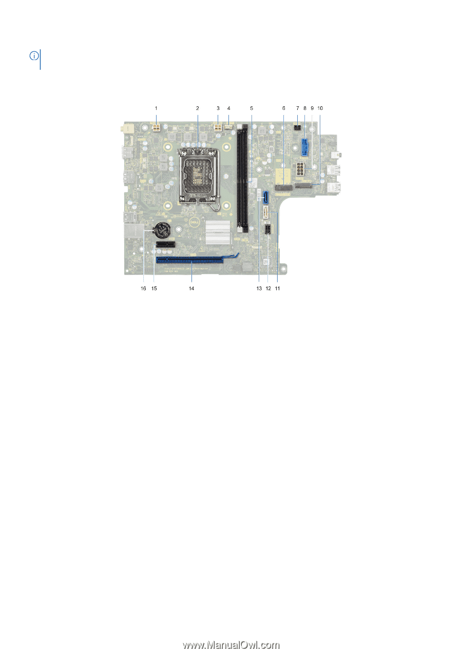
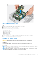
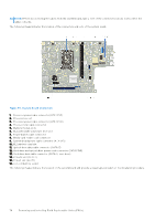
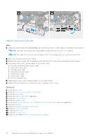
NOTE: Before disconnecting the cables from the system board, take a note of the connector locations to reconnect the cables correctly. The following image indicates the location of the connectors and slots of the system board. Figure 56. System-board connectors 1. Processor-power cable connector (ATX CPU1) 2. Processor socket 3. Processor-power cable connector (ATX CPU2) 4. Processor-fan cable connector 5. Memory module slots 6. M.2 2230/2280 solid-state drive slot 7. Power-button cable connector 8. Media-card reader cable connector 9. System-board power cable connector (ATX SYS) 10. M.2 wireless-card slot 11. Optical-drive data cable connector (SATA-3) 12. Hard-drive and optical-drive power cable connector (SATA PWR) 13. Hard-drive data cable connector (SATA-0, boot drive) 14. PCIe x16 slot (SLOT2) 15. PCIe x1 slot (SLOT1) 16. Coin-cell battery socket The following images indicate the location of the system board and provide a visual representation of the installation procedure. 74 Removing and installing Field Replaceable Units (FRUs)
-
 1
1 -
2
-
3
-
4
-
5
-
6
-
7
-
8
-
9
-
10
-
11
-
12
-
13
-
14
-
15
-
16
-
17
-
18
-
19
-
20
-
21
-
22
-
23
-
24
-
25
-
26
-
27
-
28
-
29
-
30
-
31
-
32
-
33
-
34
-
35
-
36
-
37
-
38
-
39
-
40
-
41
-
42
-
43
-
44
-
45
-
46
-
47
-
48
-
49
-
50
-
51
-
52
-
53
-
54
-
55
-
56
-
57
-
58
-
59
-
60
-
61
-
62
-
63
-
64
-
65
-
66
-
67
-
68
-
 69
69 -
 70
70 -
 71
71 -
 72
72 -
 73
73 -
 74
74 -
 75
75 -
 76
76 -
 77
77 -
 78
78 -
 79
79 -
80
-
81
-
82
-
83
-
84
-
85
-
86
-
87
-
88
-
89
-
90
-
91
-
92
-
93
-
94
-
95
-
96
-
97
-
98
-
99
-
100
 |
 |