Dell Inspiron 3582 Service Manual - Page 15
Screw list, Secured
 |
View all Dell Inspiron 3582 manuals
Add to My Manuals
Save this manual to your list of manuals |
Page 15 highlights
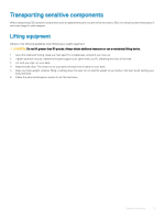
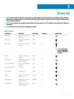
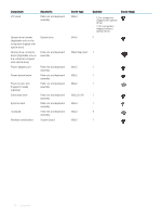
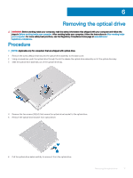
5 Screw list NOTE: When removing screws from a component, it is recommended to note the screw type, the quantity of screws, and then place them in a screw storage box. This is to ensure that the correct number of screws and correct screw type is restored when the component is replaced. NOTE: Some computers have magnetic surfaces. Ensure that the screws are not left attached to such surface when replacing a component. NOTE: Screw color may vary with the configuration ordered. Table 1. Screw list Component Base cover Base cover Base cover Secured to Palm rest and keyboard assembly Palm rest and keyboard assembly Palm rest and keyboard assembly Screw type M2x2 M2x4 M2.5x7 Quantity 2 1 6 Battery Palm rest and keyboard M2x3 4 assembly Display panel Display back-cover and M2x2 4 antenna assembly Hard-drive assembly Palm rest and keyboard M2x3 4 assembly Hard-drive bracket Hard drive M3x3 4 Thermal plate Hinges Hinge brackets Hinge brackets System board M2x3 2 Palm rest and keyboard M2.5x5 5 assembly Display back-cover and M2.5x4 8 antenna assembly Display back-cover and M2x2 2 antenna assembly Screw image NOTE: Screw color may vary depending on the configuration ordered. Screw list 15
-
 1
1 -
2
-
3
-
4
-
5
-
6
-
7
-
8
-
9
-
 10
10 -
 11
11 -
 12
12 -
 13
13 -
 14
14 -
 15
15 -
 16
16 -
 17
17 -
 18
18 -
 19
19 -
 20
20 -
21
-
22
-
23
-
24
-
25
-
26
-
27
-
28
-
29
-
30
-
31
-
32
-
33
-
34
-
35
-
36
-
37
-
38
-
39
-
40
-
41
-
42
-
43
-
44
-
45
-
46
-
47
-
48
-
49
-
50
-
51
-
52
-
53
-
54
-
55
-
56
-
57
-
58
-
59
-
60
-
61
-
62
-
63
-
64
-
65
-
66
-
67
-
68
-
69
-
70
-
71
-
72
-
73
-
74
-
75
-
76
-
77
-
78
-
79
-
80
-
81
-
82
-
83
-
84
-
85
-
86
-
87
-
88
-
89
-
90
-
91
-
92
-
93
-
94
-
95
-
96
-
97
-
98
-
99
-
100
-
101
-
102
-
103
-
104
-
105
-
106
-
107
-
108
-
109
-
110
-
111
-
112
 |
 |
