Dell Inspiron 9200 Owner's Manual - Page 88
Optical Drive, are securely attached to the Mini PCI card.
 |
View all Dell Inspiron 9200 manuals
Add to My Manuals
Save this manual to your list of manuals |
Page 88 highlights
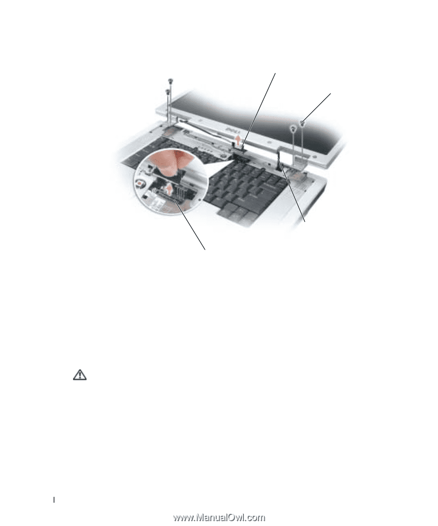
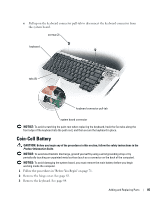
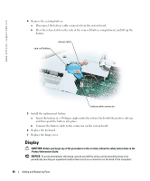
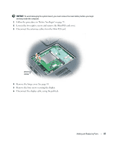
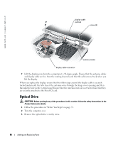
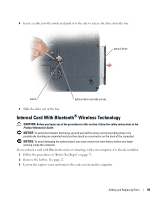
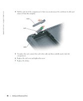
www.dell.com | support.dell.com display cable pull-tab screw (4) antenna cables display cable connector 7 Lift the display away from the computer at a 90-degree angle. Ensure that the antenna cables and display cable are free from the routing channels and that the cables move freely when you lift the display. When you replace the display, ensure that the ribbon tape around the display cable is securely tucked underneath the tabs. Insert the antenna wires through the hinge cover opening and then through the hole in the system board. Ensure that the antenna wires are not twisted and that they are securely attached to the Mini PCI card. Optical Drive CAUTION: Before you begin any of the procedures in this section, follow the safety instructions in the Product Information Guide. 1 Follow the procedures in "Before You Begin" on page 71. 2 Turn the computer over. 3 Remove the optical-drive security screw. 88 Adding and Replacing Parts
-
 1
1 -
2
-
3
-
4
-
5
-
6
-
7
-
8
-
9
-
10
-
11
-
12
-
13
-
14
-
15
-
16
-
17
-
18
-
19
-
20
-
21
-
22
-
23
-
24
-
25
-
26
-
27
-
28
-
29
-
30
-
31
-
32
-
33
-
34
-
35
-
36
-
37
-
38
-
39
-
40
-
41
-
42
-
43
-
44
-
45
-
46
-
47
-
48
-
49
-
50
-
51
-
52
-
53
-
54
-
55
-
56
-
57
-
58
-
59
-
60
-
61
-
62
-
63
-
64
-
65
-
66
-
67
-
68
-
69
-
70
-
71
-
72
-
73
-
74
-
75
-
76
-
77
-
78
-
79
-
80
-
81
-
82
-
 83
83 -
 84
84 -
 85
85 -
 86
86 -
 87
87 -
 88
88 -
 89
89 -
 90
90 -
 91
91 -
 92
92 -
 93
93 -
94
-
95
-
96
-
97
-
98
-
99
-
100
-
101
-
102
-
103
-
104
-
105
-
106
-
107
-
108
-
109
-
110
-
111
-
112
-
113
-
114
-
115
-
116
-
117
-
118
-
119
-
120
-
121
-
122
 |
 |