| Section |
Page |
| Dell™ Inspiron™ N4110 Service Manual |
1 |
| Notes, Cautions, and Warnings |
2 |
| Contents |
3 |
| Before You Begin |
9 |
| Recommended Tools |
9 |
| Turning Off Your Computer |
9 |
| Before Working Inside Your Computer |
10 |
| 2 |
13 |
| Top Cover |
13 |
| Removing the Top Cover |
13 |
| 1 Follow the instructions in \ |
13 |
| 2 Press and hold the release button that secures the top cover to the display back cover. |
13 |
| 3 Slide and lift the top cover. |
13 |
| Replacing the Top Cover |
14 |
| 1 Follow the instructions in \ |
14 |
| 2 Align the top cover to the display back cover. |
14 |
| 3 Slide the top cover until it clicks into place. Ensure that there are no gaps between the top cover and display back cover. |
14 |
| 3 |
15 |
| Battery |
15 |
| Removing the Battery |
15 |
| 1 Follow the instructions in \ |
15 |
| 2 Shut down the computer and turn it over. |
15 |
| 3 Slide the battery lock latch until it clicks into place. |
15 |
| 4 Slide the battery release latch to the unlock position. |
15 |
| 5 Slide and lift the battery out of the battery bay. |
15 |
| Replacing the Battery |
16 |
| 1 Follow the instructions in \ |
16 |
| 2 Slide the battery into the battery bay until it clicks into place. |
16 |
| 3 Slide the battery lock latch to the lock position. |
16 |
| Module Cover |
17 |
| Removing the Module Cover |
17 |
| Replacing the Module Cover |
18 |
| Optical Drive |
19 |
| Removing the Optical Drive |
19 |
| Replacing the Optical Drive |
21 |
| Memory Module(s) |
23 |
| Removing the Memory Module(s) |
23 |
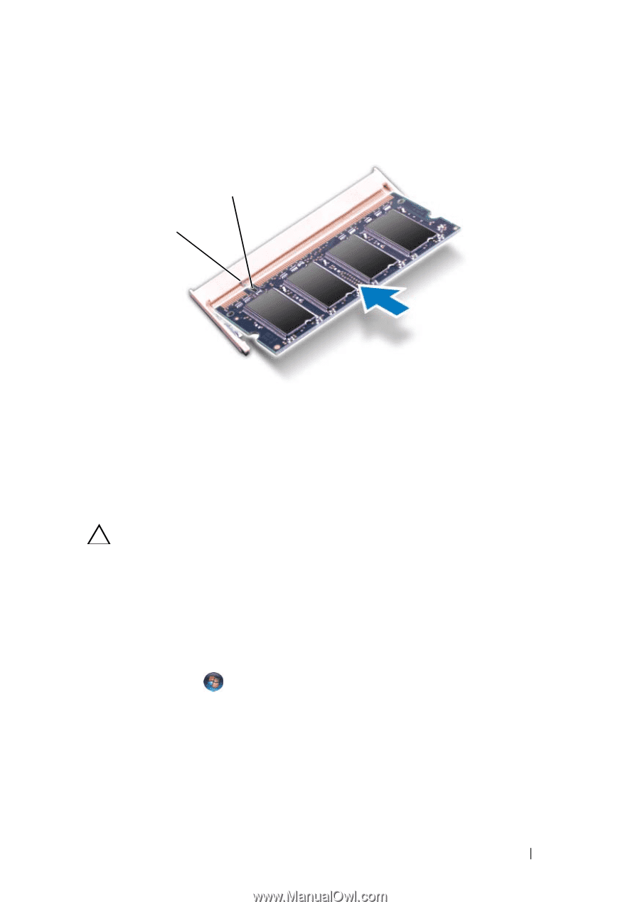
| Replacing the Memory Module(s) |
24 |
| 7 |
27 |
| Keyboard |
27 |
| Removing the Keyboard |
27 |
| 1 Follow the instructions in \ |
27 |
| 2 Remove the battery (see \ |
27 |
| 3 Turn the computer over and open the display as far as possible. |
27 |
| 4 Slide a plastic scribe between the slots on the keyboard and release the tabs on the palm rest. |
27 |
| 5 Pry and lift the keyboard to disengage it from the tabs on the palm rest. |
27 |
| 6 Ease the keyboard up until it clears off the palm rest. |
28 |
| 7 Carefully turn the keyboard over and place it on the palm-rest assembly. |
28 |
| 8 Lift the connector latch that secures the keyboard cable to the connector on the system board and disconnect the keyboard cable. |
28 |
| 9 Lift the keyboard off the computer. |
28 |
| Replacing the Keyboard |
29 |
| 1 Follow the instructions in \ |
29 |
| 2 Slide the keyboard cable into the connector on the system board. Press down on the connector latch to secure the keyboard cable to the connector on the system board. |
29 |
| 3 Slide the tabs on the keyboard into the slots on the palm-rest assembly. |
29 |
| 4 Gently press around the edges of the keyboard and slide it upwards to secure the keyboard under the tabs on the palm-rest assembly. |
29 |
| 5 Close the display and turn the computer over. |
29 |
| 6 Replace the battery (see \ |
30 |
| 8 |
31 |
| Palm-Rest Assembly |
31 |
| Removing the Palm-Rest Assembly |
31 |
| 1 Follow the instructions in \ |
31 |
| 2 Remove the battery (see \ |
31 |
| 3 Remove the module cover (see \ |
31 |
| 4 Follow the instructions from step 4 to step 5 in \ |
31 |
| 5 Remove the ten screws from the computer base. |
31 |
| 6 Remove the keyboard (see \ |
31 |
| 7 Remove the five screws on the palm-rest assembly. |
32 |
| 8 Lift the connector latches and pull the pull-tabs to disconnect the power-button cable, touch-pad cable, and hot-key board cable from the connectors on the system board. |
32 |
| 9 Using a plastic scribe, carefully pry out the palm-rest assembly along the rear edge and then ease the palm-rest assembly from the computer base. |
34 |
| 10 Lift the palm-rest assembly off the computer base. |
34 |
| 11 Turn the palm-rest assembly over. |
34 |
| 12 Remove the hot-key board (see \ |
34 |
| 13 Remove the power button board (see \ |
34 |
| Replacing the Palm-Rest Assembly |
35 |
| 1 Follow the instructions in \ |
35 |
| 2 Replace the power button board (see \ |
35 |
| 3 Replace the hot-key board (see \ |
35 |
| 4 Align the tabs on the palm-rest assembly with the slots on the computer base and gently snap the palm-rest assembly in place. |
35 |
| 5 Slide the power-button cable, touch-pad cable, and hot-key board cable into the connectors on the system board and press down on the connector latches to secure them. |
35 |
| 6 Replace the five screws on the palm-rest assembly. |
35 |
| 7 Replace the keyboard (see \ |
35 |
| 8 Turn the computer over and replace the ten screws at the bottom of the computer. |
35 |
| 9 Follow the instructions from step 4 to step 5 in \ |
35 |
| 10 Replace the module cover (see \ |
35 |
| 11 Replace the battery (see \ |
35 |
| Hot-Key Board |
37 |
| Removing the Hot-Key Board |
37 |
| Replacing the Hot-Key Board |
38 |
| Power Button Board |
41 |
| Removing the Power Button Board |
41 |
| Replacing the Power Button Board |
42 |
| 11 |
45 |
| Wireless Mini-Card(s) |
45 |
| Removing the Mini-Card(s) |
45 |
| 1 Follow the instructions in \ |
45 |
| 2 Remove the battery (see \ |
45 |
| 3 Remove the module cover (see \ |
45 |
| 4 Follow the instructions from step 4 to step 5 in \ |
46 |
| 5 Remove the keyboard (see \ |
46 |
| 6 Remove the palm-rest assembly (see \ |
46 |
| 7 Disconnect the two antenna cables from the Mini-Card(s). |
46 |
| 8 Remove the screw that secures the Mini-Card(s) to the system board. |
46 |
| 9 Lift the Mini-Card(s) off the computer base. |
46 |
| 10 If you are removing the WLAN Mini-Card, detach it from the WLAN Mini-Card bracket. |
47 |
| Replacing the Mini-Card(s) |
47 |
| 1 Follow the instructions in \ |
47 |
| 2 Remove the new Mini-Card from its packaging. |
47 |
| 3 If you are replacing the WLAN Mini-Card, attach it to the WLAN Mini-Card bracket. |
47 |
| 4 Insert the Mini-Card connector at a 45-degree angle into the system-board connector. |
47 |
| 5 Press the other end of the Mini-Card down into the slot on the system board and replace the screw that secures the Mini-Card to the system board. |
48 |
| 6 Connect the appropriate antenna cables to the Mini-Card you are installing. The following table provides the antenna cable color scheme for the Mini-Cards supported by your computer. |
48 |
| 7 Replace the palm-rest assembly (see \ |
48 |
| 8 Replace the keyboard (see \ |
48 |
| 9 Follow the instructions from step 4 to step 5 in \ |
48 |
| 10 Replace the module cover (see \ |
48 |
| 11 Replace the battery (see \ |
48 |
| 12 Install the drivers and utilities for your computer, as required. |
48 |
| 12 |
49 |
| Thermal Fan |
49 |
| Removing the Thermal Fan |
49 |
| 1 Follow the instructions in \ |
49 |
| 2 Remove the battery (see \ |
49 |
| 3 Remove the keyboard (see \ |
49 |
| 4 Remove the palm-rest assembly (see \ |
49 |
| 5 Disconnect the display cable from the connector on the system board. |
49 |
| 6 Disconnect the thermal fan cable from the connector on the system board. |
49 |
| 7 Remove the screw that secures the thermal fan to the computer base. |
49 |
| 8 Lift the thermal fan off the system board. |
49 |
| Replacing the Thermal Fan |
50 |
| 1 Follow the instructions in \ |
50 |
| 2 Place the thermal fan on the computer base and replace the screw. |
50 |
| 3 Connect the thermal fan cable to the connector on the system board. |
50 |
| 4 Connect the display cable to the connector on the system board. |
50 |
| 5 Replace the palm-rest assembly (see \ |
50 |
| 6 Replace the keyboard (see \ |
51 |
| 7 Replace the battery (see \ |
51 |
| 13 |
53 |
| Display |
53 |
| Display Assembly |
53 |
| Removing the Display Assembly |
53 |
| 1 Follow the instructions in \ |
53 |
| 2 Remove the battery (see \ |
53 |
| 3 Remove the module cover (see \ |
53 |
| 4 Follow the instructions from step 4 to step 5 in \ |
53 |
| 5 Remove the two screws from the computer base. |
53 |
| 6 Remove the keyboard (see \ |
54 |
| 7 Remove the palm-rest assembly (see \ |
54 |
| 8 Loosen the display cable grounding screw. |
54 |
| 9 Disconnect the display cable from the connector on the system board. |
54 |
| 10 Disconnect the Mini-Card antenna cables from the connectors on the Mini-Card(s) (see \ |
54 |
| 11 Remove the four screws that secure the display assembly to the computer base. |
55 |
| 12 Lift the display assembly off the computer base. |
55 |
| Replacing the Display Assembly |
56 |
| 1 Follow the instructions in \ |
56 |
| 2 Place the display assembly in position and replace the four screws that secure the display assembly to the computer base. |
56 |
| 3 Route the display cable and Mini-Card antenna cables through the routing guides. |
56 |
| 4 Connect the display cable to the connector on the system board. |
56 |
| 5 Connect the Mini-Card antenna cables to the Mini-Cards(s) (see \ |
56 |
| 6 Tighten the display cable grounding screw. |
56 |
| 7 Replace the palm-rest assembly (see \ |
57 |
| 8 Replace the keyboard (see \ |
57 |
| 9 Replace the two screws at the bottom of the computer. |
57 |
| 10 Follow the instructions from step 4 to step 5 in \ |
57 |
| 11 Replace the module cover (see \ |
57 |
| 12 Replace the battery (see \ |
57 |
| Display Bezel |
57 |
| Removing the Display Bezel |
57 |
| 1 Follow the instructions in \ |
57 |
| 2 Remove the top cover (see \ |
57 |
| 3 Remove the display assembly (see \ |
57 |
| 4 Using your fingertips, carefully pry up the inside edge of the display bezel. |
57 |
| 5 Remove the display bezel. |
57 |
| Replacing the Display Bezel |
58 |
| 1 Follow the instructions in \ |
58 |
| 2 Realign the display bezel over the display panel and gently snap it into place. |
58 |
| 3 Replace the display assembly (see \ |
58 |
| 4 Replace the top cover (see \ |
58 |
| Display Panel |
58 |
| Removing the Display Panel |
58 |
| 1 Follow the instructions in \ |
58 |
| 2 Remove the display assembly (see \ |
59 |
| 3 Remove the display bezel (see \ |
59 |
| 4 Remove the six screws that secure the display panel to the display cover. |
59 |
| 5 Note the routing of the display cable and Mini-Card(s) cables and remove the cables from the routing guides on the display cover. |
59 |
| 6 Lift the display panel off the display cover. |
59 |
| Replacing the Display Panel |
59 |
| 1 Follow the instructions in \ |
59 |
| 2 Align the screw holes on the display panel with the screw holes on the display cover and replace the six screws. |
59 |
| 3 Route the display cable through the routing guides on the display cover. |
59 |
| 4 Replace the display bezel (see \ |
59 |
| 5 Replace the display assembly (see \ |
59 |
| Display Cable |
60 |
| Removing the Display Cable |
60 |
| 1 Follow the instructions in \ |
60 |
| 2 Remove the display assembly (see \ |
60 |
| 3 Remove the display bezel (see \ |
60 |
| 4 Remove the display panel (see \ |
60 |
| 5 Turn the display panel over and place it on a clean surface. |
60 |
| 6 Lift the tape that secures the display cable to the connector on the display panel and disconnect the display cable. |
60 |
| Replacing the Display Cable |
61 |
| 1 Follow the instructions in \ |
61 |
| 2 Connect the display cable to the connector on the display panel and secure it with the tape. |
61 |
| 3 Turn the display panel over and place it on the display cover. |
61 |
| 4 Replace the display panel (see \ |
61 |
| 5 Replace the display bezel (see \ |
61 |
| 6 Replace the display assembly (see \ |
61 |
| Hinge Caps |
61 |
| Removing the Hinge Caps |
61 |
| 1 Follow the instructions in \ |
61 |
| 2 Remove the display assembly (see \ |
61 |
| 3 Remove the display bezel (see \ |
61 |
| 4 Remove the six screws that secure the display panel to the display cover. |
61 |
| 5 Turn the display panel over and keep it on a clean surface. |
61 |
| 6 Press both sides of each hinge cap and lift the hinge caps out of the display hinges. |
61 |
| Replacing the Hinge Caps |
62 |
| 1 Follow the instructions in \ |
62 |
| 2 Align the tabs on the hinge caps with the slots on the display panel brackets and snap them into place. |
62 |
| 3 Turn the display panel over and place it on the display cover. |
62 |
| 4 Replace the six screws that secure the display panel to the display cover. |
62 |
| 5 Replace the display bezel (see \ |
62 |
| 6 Replace the display assembly (see \ |
62 |
| Display Panel Brackets |
62 |
| Removing the Display Panel Brackets |
62 |
| 1 Follow the instructions in \ |
62 |
| 2 Remove the display assembly (see \ |
62 |
| 3 Remove the display bezel (see \ |
63 |
| 4 Remove the hinge caps (see \ |
63 |
| 5 Remove the four screws (two on each side) that secure the display panel brackets to the display panel. |
63 |
| Replacing the Display Panel Brackets |
63 |
| 1 Follow the instructions in \ |
63 |
| 2 Align the screw holes on the display panel vbbrackets with the screw holes on the display panel. |
63 |
| 3 Replace the four screws (two on each side) that secure the display-panel brackets to the display panel. |
63 |
| 4 Replace the hinge caps (see \ |
63 |
| 5 Replace the display bezel (see \ |
63 |
| 6 Replace the display assembly (see \ |
64 |
| Camera Module |
65 |
| Removing the Camera Module |
65 |
| Replacing the Camera Module |
66 |
| Hinge Cover |
69 |
| Removing the Hinge Cover |
69 |
| Replacing the Hinge Cover |
71 |
| VGA Connector Board |
73 |
| Removing the VGA Connector Board |
73 |
| Replacing the VGA Connector Board |
74 |
| 17 |
77 |
| System Board |
77 |
| Removing the System Board |
77 |
| 1 Follow the instructions in \ |
77 |
| 2 Press and eject any installed cards or blanks from the 8-in-1 media card reader. |
77 |
| 3 Remove the battery (see \ |
77 |
| 4 Remove the module cover (see \ |
77 |
| 5 Remove the memory module(s) (see \ |
77 |
| 6 Follow the instructions from step 4 to step 5 in \ |
77 |
| 7 Disconnect the AC-adapter connector cable from the connector on the system board. |
77 |
| 8 Remove the keyboard (see \ |
78 |
| 9 Remove the palm-rest assembly (see \ |
78 |
| 10 Remove the thermal fan (see \ |
78 |
| 11 Loosen the display cable grounding screw. |
78 |
| 12 Disconnect the display cable and speakers cable from the connectors on the system board. |
78 |
| 13 Remove the five screws that secure the system board to the computer base. |
78 |
| 14 Lift the system board assembly to disconnect the connector on the system board from the connector on the I/O board. |
79 |
| 15 Turn the system board over. |
80 |
| 16 Remove the coin-cell battery (see \ |
80 |
| 17 Follow the instructions from step 3 to step 5 in \ |
80 |
| 18 Remove the thermal cooling assembly (see \ |
80 |
| 19 Remove the processor module (see \ |
80 |
| Replacing the System Board |
81 |
| 1 Follow the instructions in \ |
81 |
| 2 Replace the processor module (see \ |
81 |
| 3 Replace the thermal cooling assembly (see \ |
81 |
| 4 Follow the instructions from step 5 to step 7 in \ |
81 |
| 5 Replace the coin-cell battery (see \ |
81 |
| 6 Turn the system board over. |
81 |
| 7 Align the connectors on the system board with the slots on the computer base and place it in position. |
81 |
| 8 Gently press the system board to connect the connector on the system board to the connector on the I/O board. |
81 |
| 9 Replace the five screws that secure the system board to the computer base. |
81 |
| 10 Connect the display cable and speakers cable to the connectors on the system board. |
81 |
| 11 Tighten the display cable grounding screw. |
81 |
| 12 Replace the thermal fan (see \ |
81 |
| 13 Replace the palm-rest assembly (see \ |
81 |
| 14 Replace the keyboard (see \ |
81 |
| 15 Connect the AC-adapter connector cable to the connector on the system board. |
81 |
| 16 Follow the instructions from step 4 to step 5 in \ |
81 |
| 17 Replace the memory module(s) (see \ |
81 |
| 18 Replace the module cover (see \ |
81 |
| 19 Replace the battery (see \ |
81 |
| 20 Replace any cards or blanks removed from the 8-in-1 media card reader. |
82 |
| 21 Turn on the computer. |
82 |
| 22 Enter the service tag (see \ |
82 |
| Entering the Service Tag in the BIOS |
82 |
| 1 Ensure that the AC adapter is plugged in and that the main battery is installed properly. |
82 |
| 2 Turn on the computer. |
82 |
| 3 Press <F2> as soon as you see the Dell logo to enter the system setup program. |
82 |
| 4 Navigate to the security tab and enter the service tag in the Set Service Tag field. |
82 |
| 18 |
83 |
| Speakers |
83 |
| Removing the Speakers |
83 |
| 1 Follow the instructions in \ |
83 |
| 2 Follow the instructions from step 2 to step 14 in \ |
83 |
| 3 Note the speakers cable routing and lift the left and right speakers along with the its cable from the computer base. |
83 |
| Replacing the Speakers |
84 |
| 1 Follow the instructions in \ |
84 |
| 2 Place the speakers on the computer base and route the speakers cable through the routing guides. |
84 |
| 3 Follow the instructions from step 7 to step 20 in \ |
84 |
| 19 |
87 |
| Coin-Cell Battery |
87 |
| Removing the Coin-Cell Battery |
87 |
| 1 Follow the instructions in \ |
87 |
| 2 Follow the instructions from step 2 to step 15 in \ |
87 |
| 3 Use a plastic scribe and gently pry the coin-cell out of the battery socket on the system board. |
87 |
| 4 Lift the coin-cell battery out of the system-board socket. |
87 |
| Replacing the Coin-Cell Battery |
88 |
| 1 Follow the instructions in \ |
88 |
| 2 Hold the coin-cell battery with the positive side up. |
88 |
| 3 Slide the coin-cell battery into the slot and gently press until it snaps in place. |
88 |
| 4 Follow the instructions from step 6 to step 20 in \ |
88 |
| Thermal Cooling Assembly |
89 |
| Removing the Thermal Cooling Assembly |
89 |
| Replacing the Thermal Cooling Assembly |
90 |
| 21 |
91 |
| Processor Module |
91 |
| Removing the Processor Module |
91 |
| 1 Follow the instructions in \ |
91 |
| 2 Follow the instructions from step 2 to step 15 in \ |
91 |
| 3 Remove the thermal cooling assembly (see \ |
91 |
| 4 To loosen the ZIF socket, use a small, flat-blade screwdriver and rotate the ZIF-socket cam screw counterclockwise until it comes to the cam stop. |
91 |
| 5 Lift the processor module from the ZIF socket. |
91 |
| Replacing the Processor Module |
92 |
| 1 Follow the instructions in \ |
92 |
| 2 Align the pin-1 corner of the processor module with the pin-1 corner of the ZIF socket, then insert the processor module. |
92 |
| 3 Tighten the ZIF socket by turning the cam screw clockwise to secure the processor module to the system board. |
93 |
| 4 Replace the thermal cooling assembly (see \ |
93 |
| 5 Follow the instructions from step 6 to step 20 in \ |
93 |
| 22 |
95 |
| Hard-Drive Assembly |
95 |
| Removing the Hard-Drive Assembly |
95 |
| 1 Follow the instructions in \ |
95 |
| 2 Follow the instructions from step 2 to step 15 in \ |
95 |
| 3 Remove the screw that secures the hard-drive assembly to the system board. |
95 |
| 4 Slide the hard-drive assembly in the direction shown in the illustration to disconnect it from the connector on the system board. |
96 |
| 5 Lift the hard-drive assembly off the system board. |
96 |
| 6 Remove the four screws that secure the hard-drive bracket to the hard drive. |
96 |
| 7 Lift the hard drive away from the hard-drive bracket. |
96 |
| Replacing the Hard-Drive Assembly |
97 |
| 1 Follow the instructions in \ |
97 |
| 2 Remove the new hard drive from its packaging. |
97 |
| 3 Place the hard drive in the hard-drive bracket. |
97 |
| 4 Replace the four screws that secure the hard-drive bracket to the hard drive. |
97 |
| 5 Place the hard-drive assembly on the system board. |
97 |
| 6 Slide the hard-drive assembly to connect it to the connector on the system board. |
97 |
| 7 Replace the screw that secures the hard-drive assembly to the system board. |
97 |
| 8 Follow the instructions from step 6 to step 20 in \ |
98 |
| I/O Board |
99 |
| Removing the I/O Board |
99 |
| Replacing the I/O Board |
100 |
| 24 |
101 |
| AC-Adapter Connector |
101 |
| Removing the AC-Adapter Connector |
101 |
| 1 Follow the instructions in \ |
101 |
| 2 Follow the instructions from step 2 to step 14 in \ |
101 |
| 3 Remove the display assembly (see \ |
101 |
| 4 Remove the hinge cover (see \ |
101 |
| 5 Remove the VGA connector board (see \ |
101 |
| 6 Note the AC-adapter connector cable routing and remove the cable from the routing guides. |
101 |
| 7 Remove the screw that secures the AC-adapter connector to the computer base. |
101 |
| 8 Lift the AC-adapter connector off the computer base. |
101 |
| Replacing the AC-Adapter Connector |
102 |
| 1 Follow the instructions in \ |
102 |
| 2 Place the AC-adapter connector on the computer base. |
102 |
| 3 Replace the screw that secures the AC-adapter connector to the computer base. |
102 |
| 4 Route the AC-adapter connector cable through the routing guides. |
102 |
| 5 Replace the VGA connector board (see \ |
102 |
| 6 Replace the hinge cover (see \ |
102 |
| 7 Replace the display assembly (see \ |
102 |
| 8 Follow the instructions from step 7 to step 20 in \ |
102 |
| 25 |
105 |
| Flashing the BIOS |
105 |
| 1 Turn on the computer. |
105 |
| 2 Go to support.dell.com/support/downloads. |
105 |
| 3 Locate the BIOS update file for your computer: |
105 |
| a Click Enter a Tag. |
105 |
| b Enter your computer’s Service Tag in the Enter a service tag: field, click Go, and proceed to step 4. |
105 |
| a Click Select Model. |
105 |
| b Select the type of product in the Select Your Product Family list. |
105 |
| c Select the product brand in the Select Your Product Line list. |
105 |
| d Select the product model number in the Select Your Product Model list. |
105 |
| e Click Confirm. |
105 |
| 4 A list of results appear on the screen. Click BIOS. |
105 |
| 5 Click Download Now to download the latest BIOS file. The File Download window appears. |
105 |
| 6 Click Save to save the file on your desktop. The file downloads to your desktop. |
105 |
| 7 Click Close if the Download Complete window appears. The file icon appears on your desktop and is titled the same as the downloaded BIOS update file. |
105 |
 1
1 20
20 21
21 22
22 23
23 24
24 25
25 26
26 27
27 28
28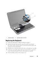 29
29 30
30