Dell Inspiron One 2330 Owner's Manual (PDF) - Page 88
Replacing the I/O Board Shield, Procedure, Postrequisites
 |
View all Dell Inspiron One 2330 manuals
Add to My Manuals
Save this manual to your list of manuals |
Page 88 highlights
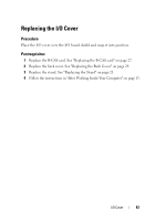
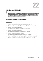
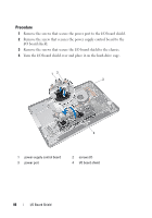
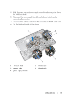
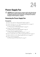
Replacing the I/O Board Shield Procedure 1 Connect the power-supply fan cable and infrared cable to the system-board connectors. 2 Connect the antenna cable to the connector on the TV tuner card. 3 Slide the power port and the power-supply control board through the slot on the I/O board shield. 4 Align the screw holes on the I/O board shield with the screw holes on the chassis. 5 Replace the screws that secure the I/O board shield to the chassis. 6 Replace the screw that secures the power-supply control board to the I/O board shield. 7 Replace the screws that secure the power port to the I/O board shield. Postrequisites 1 Replace the I/O cover. See "Replacing the I/O Cover" on page 83. 2 Replace the B-CAS card. See "Replacing the B-CAS card" on page 27. 3 Replace the power-supply fan bracket. See "Replacing the Power-Supply Fan Bracket" on page 79. 4 Replace the system-board shield. See "Replacing the System-Board Shield" on page 51. 5 Replace the VESA-mount bracket. See "Replacing the VESA-Mount Bracket" on page 44. 6 Replace the back cover. See "Replacing the Back Cover" on page 24. 7 Replace the stand. See "Replacing the Stand" on page 21. 8 Follow the instructions in "After Working Inside Your Computer" on page 13. 88 I/O Board Shield
-
 1
1 -
2
-
3
-
4
-
5
-
6
-
7
-
8
-
9
-
10
-
11
-
12
-
13
-
14
-
15
-
16
-
17
-
18
-
19
-
20
-
21
-
22
-
23
-
24
-
25
-
26
-
27
-
28
-
29
-
30
-
31
-
32
-
33
-
34
-
35
-
36
-
37
-
38
-
39
-
40
-
41
-
42
-
43
-
44
-
45
-
46
-
47
-
48
-
49
-
50
-
51
-
52
-
53
-
54
-
55
-
56
-
57
-
58
-
59
-
60
-
61
-
62
-
63
-
64
-
65
-
66
-
67
-
68
-
69
-
70
-
71
-
72
-
73
-
74
-
75
-
76
-
77
-
78
-
79
-
80
-
81
-
82
-
 83
83 -
 84
84 -
 85
85 -
 86
86 -
 87
87 -
 88
88 -
 89
89 -
 90
90 -
 91
91 -
 92
92 -
 93
93 -
94
-
95
-
96
-
97
-
98
-
99
-
100
-
101
-
102
-
103
-
104
-
105
-
106
-
107
-
108
-
109
-
110
-
111
-
112
-
113
-
114
-
115
-
116
-
117
-
118
-
119
-
120
-
121
-
122
-
123
-
124
-
125
-
126
-
127
-
128
-
129
-
130
-
131
-
132
-
133
-
134
-
135
-
136
-
137
-
138
-
139
-
140
-
141
-
142
-
143
-
144
-
145
-
146
-
147
-
148
-
149
-
150
-
151
-
152
-
153
-
154
-
155
-
156
-
157
-
158
 |
 |