Dell Inspiron Zino 300 Inspiron Zino Service Manual
Dell Inspiron Zino 300 Manual
 |
View all Dell Inspiron Zino 300 manuals
Add to My Manuals
Save this manual to your list of manuals |
Dell Inspiron Zino 300 manual content summary:
- Dell Inspiron Zino 300 | Inspiron Zino Service Manual - Page 1
Dell™ Inspiron™ 300/400 Service Manual Technical Overview Before You Begin Top Cover Bottom Cover Top Bracket I/O Bezel Optical Drive Drive Bay Power-Button Bracket Coin-Cell Battery Hard Drive Wireless Mini-Card (Inspiron 400 Only) Memory Module(s) Processor Heat Sink (Inspiron 400 Only) - Dell Inspiron Zino 300 | Inspiron Zino Service Manual - Page 2
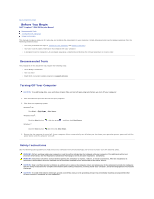
Begin Dell™ Inspiron™ 300/400 Service Manual Recommended Tools Turning Off Your Computer Safety Instructions This manual provides procedures tools: l Small Phillips screwdriver l Hex nut driver l Flash BIOS executable update program at support.dell.com Turning Off Your Computer CAUTION: To avoid - Dell Inspiron Zino 300 | Inspiron Zino Service Manual - Page 3
CAUTION: When you disconnect a cable, pull on its connector or on its pull-tab, not on the cable itself. As you pull connectors apart, keep them evenly aligned to avoid bending any connector pins. Also, before you connect a cable, ensure that both connectors are correctly oriented and aligned. - Dell Inspiron Zino 300 | Inspiron Zino Service Manual - Page 4
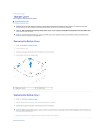
Back to Contents Page Bottom Cover Dell™ Inspiron™ 300/400 Service Manual Removing the Bottom Cover Replacing the Bottom Cover WARNING: Before working inside your computer, read the safety information that shipped with your computer. For additional - Dell Inspiron Zino 300 | Inspiron Zino Service Manual - Page 5
- Dell Inspiron Zino 300 | Inspiron Zino Service Manual - Page 6
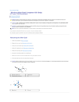
(Inspiron 400 Only) Dell™ Inspiron™ 300/400 Service Manual Removing NOTE: Dell does not guarantee compatibility or provide support for Mini-Cards from sources other than Dell. If "Protecting Against Electrostatic Discharge" in the safety instructions that shipped with your computer). 1 antenna - Dell Inspiron Zino 300 | Inspiron Zino Service Manual - Page 7
appropriate antenna cables to the Mini-Card you are installing. The following table provides the antenna cable color scheme for the Mini- Card supported by your computer. Connectors on the Mini-Card Antenna Cable Color Scheme WLAN (2 antenna cables) Main WLAN (white triangle) white Auxiliary WLAN - Dell Inspiron Zino 300 | Inspiron Zino Service Manual - Page 8
Back to Contents Page Coin-Cell Battery Dell™ Inspiron™ 300/400 Service Manual Removing the Coin-Cell Battery Replacing the manufacturer's instructions. CAUTION: Only a certified service technician should perform repairs on your computer. Damage due to servicing that is not authorized by Dell™ is - Dell Inspiron Zino 300 | Inspiron Zino Service Manual - Page 9
5. Replace the top bracket (see Replacing the Top Bracket). 6. Replace the top cover (see Replacing the Top Cover). CAUTION: Before turning on the computer, replace all screws and ensure that no stray screws remain inside the computer. Failure to do so may result in damage to the computer. 7. - Dell Inspiron Zino 300 | Inspiron Zino Service Manual - Page 10
Back to Contents Page Graphics Card (Inspiron 400 Only) Dell™ Inspiron™ 300/400 Service Manual Removing the Graphics Card Replacing the Graphics Card WARNING: Before working inside your computer, read the safety information that shipped with your computer. For additional - Dell Inspiron Zino 300 | Inspiron Zino Service Manual - Page 11
7. Connect your computer and all attached devices to electrical outlets, and turn them on. Back to Contents Page - Dell Inspiron Zino 300 | Inspiron Zino Service Manual - Page 12
Back to Contents Page Graphics-Card Fan (Inspiron 400 Only) Dell™ Inspiron™ 300/400 Service Manual Removing the Graphics-Card Fan Replacing the Graphics-Card Fan WARNING: Before working inside your computer, read the safety information that shipped with your computer. - Dell Inspiron Zino 300 | Inspiron Zino Service Manual - Page 13
- Dell Inspiron Zino 300 | Inspiron Zino Service Manual - Page 14
Contents Page Graphics-Card Heat Sink (Inspiron 400 Only) Dell™ Inspiron™ 300/400 Service Manual Removing the Graphics-Card Heat Sink these steps incorrectly could damage your system board. For technical service information, see the Setup Guide. Removing the Graphics-Card Heat Sink 1. Follow the - Dell Inspiron Zino 300 | Inspiron Zino Service Manual - Page 15
Back to Contents Page - Dell Inspiron Zino 300 | Inspiron Zino Service Manual - Page 16
Dell™ Inspiron™ 300/400 Service Manual support for hard drives from sources other than Dell. NOTE: If you are installing a hard drive from a source other than Dell, you need to install an operating system, drivers, and utilities on the new hard drive (see the Dell Technology Guide instructions that - Dell Inspiron Zino 300 | Inspiron Zino Service Manual - Page 17
to electrical outlets, and turn them on. 10. Install the operating system for your computer, as needed. See "Restoring Your Operating System" in the Setup Guide. 11. Install the drivers and utilities for your computer, as needed. For more information, see the - Dell Inspiron Zino 300 | Inspiron Zino Service Manual - Page 18
Back to Contents Page Drive Bay Dell™ Inspiron™ 300/400 Service Manual Removing the Drive Bay Replacing the Drive Bay WARNING: Before working inside your computer, read the safety information that shipped with your computer. For additional - Dell Inspiron Zino 300 | Inspiron Zino Service Manual - Page 19
3. Align the tabs on the drive bay with the slots on the chassis. Slide the drive bay to align the screw holes on the drive bay with the screws holes on the system board. 4. Replace the two screws that secure the drive bay to the system board. 5. Replace the screw that secures the power-button - Dell Inspiron Zino 300 | Inspiron Zino Service Manual - Page 20
Contents Page Processor Heat Sink (Inspiron 400 Only) Dell™ Inspiron™ 300/400 Service Manual Removing the Processor Heat Sink Replacing steps incorrectly could damage your system board. For technical service information, see the Setup Guide. Removing the Processor Heat Sink 1. Follow the procedures - Dell Inspiron Zino 300 | Inspiron Zino Service Manual - Page 21
CAUTION: Incorrect alignment of the processor heat sink can cause damage to the system board and processor. NOTE: The original thermal grease can be reused if the original processor and processor heat sink are reinstalled together. If either the processor or the processor heat sink is replaced, use - Dell Inspiron Zino 300 | Inspiron Zino Service Manual - Page 22
Back to Contents Page I/O Bracket Dell™ Inspiron™ 300/400 Service Manual Removing the I/O Bracket Replacing the I/O Bezel). 5. Remove the chassis fan (see Removing the Chassis Fan). 6. Using a hex nut driver, remove the two screws that secure the VGA connector to the I/O bracket. 7. Remove the screw - Dell Inspiron Zino 300 | Inspiron Zino Service Manual - Page 23
4. Using a hex nut driver, replace the two screws that secure the VGA connector to the I/O bracket. 5. Replace the chassis fan (see Replacing the Chassis Fan). 6. Replace the I/O bezel (see - Dell Inspiron Zino 300 | Inspiron Zino Service Manual - Page 24
Back to Contents Page I/O Bezel Dell™ Inspiron™ 300/400 Service Manual Removing the I/O Bezel Replacing the I/O Bezel WARNING: Before working inside your computer, read the safety information that shipped with your computer. For additional safety best - Dell Inspiron Zino 300 | Inspiron Zino Service Manual - Page 25
Back to Contents Page - Dell Inspiron Zino 300 | Inspiron Zino Service Manual - Page 26
Back to Contents Page Memory Module(s) Dell™ Inspiron™ 300/400 Service Manual Inspiron 300 Inspiron 400 WARNING: Before working inside your computer, read the safety information that shipped with your computer. For additional safety best practices information, see the Regulatory - Dell Inspiron Zino 300 | Inspiron Zino Service Manual - Page 27
® System and Maintenance. Click the Start button ® Control Panel® System and Security® System. 11. Check the amount of memory (RAM) listed. Inspiron 400 Removing the Memory Module(s) 1. Follow the procedures in Before You Begin. 2. Remove the bottom cover (see Removing the Bottom Cover). CAUTION - Dell Inspiron Zino 300 | Inspiron Zino Service Manual - Page 28
3. Use your fingertips to carefully spread apart the securing clips on each end of the memory-module connector until the module pops up. 4. Remove the memory module from the memory-module connector. 1 tab 3 memory module 2 memory-module connector 4 securing clips (2) Replacing the Memory Module - Dell Inspiron Zino 300 | Inspiron Zino Service Manual - Page 29
Back to Contents Page Optical Drive Dell™ Inspiron™ 300/400 Service Manual Removing the Optical Drive Replacing the Optical Drive WARNING: Before working inside your computer, read the safety information that shipped with your computer. For additional - Dell Inspiron Zino 300 | Inspiron Zino Service Manual - Page 30
5. Replace the top bracket (see Replacing the Top Bracket). 6. Replace the top cover (see Replacing the Top Cover). CAUTION: Before turning on the computer, replace all screws and ensure that no stray screws remain inside the computer. Failure to do so may result in damage to the computer. 7. - Dell Inspiron Zino 300 | Inspiron Zino Service Manual - Page 31
Back to Contents Page Processor (Inspiron 400 Only) Dell™ Inspiron™ 300/400 Service Manual Removing the Processor Replacing the Processor WARNING: Before working inside your computer, read the safety information that shipped with your computer. For additional safety best - Dell Inspiron Zino 300 | Inspiron Zino Service Manual - Page 32
Replacing the Processor CAUTION: Ground yourself by touching an unpainted metal surface or the computer stand. CAUTION: When replacing the processor, do not touch any of the pins inside the socket or allow any objects to fall on the pins in the socket. 1. Follow the procedures in Before You Begin. - Dell Inspiron Zino 300 | Inspiron Zino Service Manual - Page 33
13. Replace the optical drive (see Replacing the Optical Drive). 14. Replace the top bracket (see Replacing the Top Bracket). 15. Replace the top cover (see Replacing the Top Cover). CAUTION: Before turning on the computer, replace all screws and ensure that no stray screws remain inside the - Dell Inspiron Zino 300 | Inspiron Zino Service Manual - Page 34
Back to Contents Page Power-Button Bracket Dell™ Inspiron™ 300/400 Service Manual Removing the Power-Button Bracket Replacing the Power-Button Bracket WARNING: Before working inside your computer, read the safety information that shipped with your computer. - Dell Inspiron Zino 300 | Inspiron Zino Service Manual - Page 35
5. Replace the optical drive (see Replacing the Optical Drive). 6. Replace the top bracket (see Replacing the Top Bracket). 7. Replace the top cover (see Replacing the Top Cover). CAUTION: Before turning on the computer, replace all screws and ensure that no stray screws remain inside the computer. - Dell Inspiron Zino 300 | Inspiron Zino Service Manual - Page 36
Back to Contents Page Chassis Fan Dell™ Inspiron™ 300/400 Service Manual Removing the Chassis Fan Replacing the Chassis Fan WARNING: Before working inside your computer, read the safety information that shipped with your computer. For additional - Dell Inspiron Zino 300 | Inspiron Zino Service Manual - Page 37
3. Replace the four screws that secure the chassis fan to the I/O bracket. 4. Connect the chassis fan cable to the connector on the system board. 5. Replace the I/O bezel (see Replacing the I/O Bezel). 6. Replace the top bracket (see Replacing the Top Bracket). 7. Replace the top cover (see - Dell Inspiron Zino 300 | Inspiron Zino Service Manual - Page 38
Back to Contents Page System Board Dell™ Inspiron™ 300/400 Service Manual Removing the System Board Replacing the System Board Entering the Service Tag in the BIOS WARNING: Before working inside your computer, read the safety information that shipped with your computer. For additional safety best - Dell Inspiron Zino 300 | Inspiron Zino Service Manual - Page 39
on the chassis and slide the system board in place. 3. Replace the four screws that secure the system board to the chassis. 4. For Inspiron 400 Only: a. Replace the graphics-card fan (see Replacing the Graphics-Card Fan). b. Replace the graphics card (see Replacing the Graphics Card). c. Replace - Dell Inspiron Zino 300 | Inspiron Zino Service Manual - Page 40
the computer. NOTE: After you have replaced the system board, enter the computer's Service Tag into the BIOS of the replacement system board. 17. Enter the Service Tag (see Entering the Service Tag in the BIOS). Entering the Service Tag in the BIOS 1. Turn on the computer. 2. Press during POST - Dell Inspiron Zino 300 | Inspiron Zino Service Manual - Page 41
Dell™ Inspiron™ 300/400 Service Manual on (or restart) your computer. 2. When the DELL™ logo is displayed, watch for the F2 prompt to . System Info System BIOS Version Service Tag Asset Tag Processor Type Processor L2 number Displays the service tag of the computer when the service tag is present - Dell Inspiron Zino 300 | Inspiron Zino Service Manual - Page 42
SATA-1 eSATA-0 (applicable for Inspiron 400 computer only) eSATA-1 (applicable for Inspiron 400 computer only) Keyboard Errors Displays the service tag of the computer if the service tag is present or provides a field to input the service tag manually when the service tag is absent Displays current - Dell Inspiron Zino 300 | Inspiron Zino Service Manual - Page 43
Boot You can use this feature to change the current boot sequence, for example, to boot from the CD/DVD drive to run the Dell Diagnostics on the Drivers and Utilities media. On completion of diagnostic tests, the previous boot sequence is restored. 1. If you are booting to a USB device, connect the - Dell Inspiron Zino 300 | Inspiron Zino Service Manual - Page 44
any of the procedures in this section, follow the safety instructions that shipped with your computer. WARNING: The computer must certified service technician should perform repairs on your computer. Damage due to servicing that is not authorized by Dell™ is replace it on pins 2 and 3. Inspiron 300 - Dell Inspiron Zino 300 | Inspiron Zino Service Manual - Page 45
Inspiron 400 10. Replace the drive bay (see Replacing the Drive Bay). Turn on the computer. 2. Go to the Dell Support website at support.dell.com. 3. Click Drivers & Downloads® Select Model. 4. Locate the BIOS update file for your computer: NOTE: The Service Tag for your computer is located at the - Dell Inspiron Zino 300 | Inspiron Zino Service Manual - Page 46
8. Click Close if the Download Complete window appears. The file icon appears on your desktop and is titled the same as the downloaded BIOS update file. 9. Double-click the file icon on the desktop and follow the instructions on the screen. Back to Contents Page - Dell Inspiron Zino 300 | Inspiron Zino Service Manual - Page 47
Back to Contents Page Technical Overview Dell™ Inspiron™ 300/400 Service Manual Inspiron™ 300 Inspiron 400 WARNING: Before working inside your computer, read the safety information that shipped with your computer. For additional safety best practices information, see the Regulatory - Dell Inspiron Zino 300 | Inspiron Zino Service Manual - Page 48
(SATA1) 5 optical drive power connector (ODD_PWR1) 6 CMOS jumper (CMOS1) 7 memory-module connector (DIMM1) 8 processor 9 chassis fan connector (SYSFAN1) Inspiron 400 Inside View 1 chassis fan 3 drive bay 5 processor heat sink 2 coin-cell battery 4 optical drive System Board Components - Dell Inspiron Zino 300 | Inspiron Zino Service Manual - Page 49
1 processor socket 2 processor 3 chassis fan connector (CPU_FAN) 4 SATA power connector (SATAPWR1) 5 CMOS jumper (JP1) 6 coin-cell battery socket (BT1) 7 SATA drive connector (SATA2) 8 SATA drive connector (SATA1) 9 SATA power connector (SATAPWR2) Back to Contents Page - Dell Inspiron Zino 300 | Inspiron Zino Service Manual - Page 50
to Contents Page Dell™ Inspiron™ 300/400 Service Manual NOTE: A NOTE indicates important information that helps you make better use of your computer. CAUTION: A CAUTION indicates either potential damage to hardware or loss of data and tells you how to avoid the problem. WARNING: A WARNING indicates - Dell Inspiron Zino 300 | Inspiron Zino Service Manual - Page 51
Back to Contents Page Top Bracket Dell™ Inspiron™ 300/400 Service Manual Removing the Top Bracket Replacing the Top Bracket WARNING: Before working inside your computer, read the safety information that shipped with your computer. For additional - Dell Inspiron Zino 300 | Inspiron Zino Service Manual - Page 52
the top bracket with the slots on the chassis and place the top bracket. 3. Replace the screw that secures the top bracket to the computer. 4. Inspiron 400 - Align the screw holes on the wireless antennas with the screw holes on the top bracket. Replace the two screws that secure the wireless - Dell Inspiron Zino 300 | Inspiron Zino Service Manual - Page 53
Back to Contents Page Top Cover Dell™ Inspiron™ 300/400 Service Manual Removing the Top Cover Replacing the Top Cover WARNING: Before working inside your computer, read the safety information that shipped with your computer. For additional
-
 1
1 -
 2
2 -
 3
3 -
 4
4 -
 5
5 -
 6
6 -
 7
7 -
8
-
9
-
10
-
11
-
12
-
13
-
14
-
15
-
16
-
17
-
18
-
19
-
20
-
21
-
22
-
23
-
24
-
25
-
26
-
27
-
28
-
29
-
30
-
31
-
32
-
33
-
34
-
35
-
36
-
37
-
38
-
39
-
40
-
41
-
42
-
43
-
44
-
45
-
46
-
47
-
48
-
49
-
50
-
51
-
52
-
53
 |
 |
Dell™ Inspiron™ 300/400 Service Manual
Notes, Cautions, and Warnings
Information in this document is subject to change without notice.
© 2009 Dell Inc. All rights reserved.
Reproduction of these materials in any manner whatsoever without the written permission of Dell Inc. is strictly forbidden.
Trademarks used in this text:
Dell
, the
DELL
logo, and
Inspiron
are trademarks of Dell Inc.;
Microsoft
,
Windows
,
Windows Vista
, and
Windows Vista
start button logo are either
trademarks or registered trademarks of Microsoft Corporation in the United States and/or other countries.
Other trademarks and trade names may be used in this document to refer to either the entities claiming the marks and names or their products. Dell Inc. disclaims any
proprietary interest in trademarks and trade names other than its own.
Regulatory Model D02U series
Regulatory Type D02U001 and D02U002
September 2009
Rev. A00
Technical Overview
Before You Begin
Top Cover
Bottom Cover
Top Bracket
I/O Bezel
Optical Drive
Drive Bay
Power
-
Button Bracket
Coin
-
Cell Battery
Hard Drive
Wireless Mini
-
Card (Inspiron 400 Only)
Memory Module(s)
Processor Heat Sink (Inspiron 400 Only)
Processor (Inspiron 400 Only)
Chassis Fan
I/O Bracket
Graphics
-
Card Heat Sink (Inspiron 400 Only)
Graphics Card (Inspiron 400 Only)
Graphics
-
Card Fan (Inspiron 400 Only)
System Board
System Setup Utility
NOTE:
A NOTE indicates important information that helps you make better use of your computer.
CAUTION:
A CAUTION indicates either potential damage to hardware or loss of data and tells you how to avoid the problem.
WARNING:
A WARNING indicates a potential for property damage, personal injury, or death.