Dell Latitude 14 Rugged Dell Latitude 14 Rugged 5404Series Owners Manual - Page 31
Installing the USH Board, Removing the Driving Board, Optical Drive, Bottom Cover, Hard Drive, Battery
 |
View all Dell Latitude 14 Rugged manuals
Add to My Manuals
Save this manual to your list of manuals |
Page 31 highlights
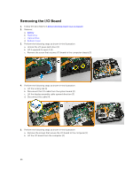
c. Optical Drive d. Bottom Cover 3. Perform the following steps as shown in the illustration: a. Lift the locking tab [1]. b. Disconnect the USH board cables from the connectors [2]. c. Remove the screws that secure the board [3]. d. Lift and flip the board at an angle to access the smart card cable at the bottom [4]. e. Lift the locking tab [5]. f. Disconnect the smart card cable and release the USH board from the computer chassis [6]. 4. Remove the USH board from the computer. Installing the USH Board 1. Connect the smart card cable to the USH board at the bottom of the board. 2. Flip the USH board to replace it to its original position. 3. Tighten the screws to secure the USH board. 4. Connect the cables to the USH board. 5. Install: a. Bottom Cover b. Optical Drive c. Hard Drive d. Battery 6. Follow the procedures in After Working Inside Your computer Removing the Driving Board 1. Follow the procedures in Before Working Inside Your Computer 2. Remove: a. Battery b. Hard Drive c. Optical Drive d. Bottom Cover 3. Perform the following steps as shown in the illustration: a. Peel the adhesive tape [1]. b. Disconnect the display assembly cable [2]. c. Peel the adhesive tape [3]. d. Disconnect the I/O cable [4] 31
-
 1
1 -
2
-
3
-
4
-
5
-
6
-
7
-
8
-
9
-
10
-
11
-
12
-
13
-
14
-
15
-
16
-
17
-
18
-
19
-
20
-
21
-
22
-
23
-
24
-
25
-
 26
26 -
 27
27 -
 28
28 -
 29
29 -
 30
30 -
 31
31 -
 32
32 -
 33
33 -
 34
34 -
 35
35 -
 36
36 -
37
-
38
-
39
-
40
-
41
-
42
-
43
-
44
-
45
-
46
-
47
-
48
-
49
-
50
-
51
-
52
-
53
-
54
-
55
-
56
-
57
-
58
 |
 |
