Dell Latitude 3540 Owners Manual - Page 21
Installing the Input/Output (I/O) Board, Removing the System Board
 |
View all Dell Latitude 3540 manuals
Add to My Manuals
Save this manual to your list of manuals |
Page 21 highlights
Installing the Input/Output (I/O) Board 1. Place the I/O board in its slot. 2. Tighten the screw to secure the I/O board to the computer. 3. Connect the I/O cable to the system board. 4. Install: a) palmrest b) keyboard c) access panel d) battery 5. Follow the procedures in After Working Inside Your Computer. Removing the System Board 1. Follow the procedures in Before Working Inside Your Computer. 2. Remove: a) SD card b) battery c) access panel d) memory module e) hard drive f) optical drive g) keyboard h) palmrest i) WLAN card 3. Disconnect the following cables: a) display cable b) power-connector port cable c) speaker cable d) I/O board cable e) Touch cable (for touch computer only) 21
-
 1
1 -
2
-
3
-
4
-
5
-
6
-
7
-
8
-
9
-
10
-
11
-
12
-
13
-
14
-
15
-
 16
16 -
 17
17 -
 18
18 -
 19
19 -
 20
20 -
 21
21 -
 22
22 -
 23
23 -
 24
24 -
 25
25 -
 26
26 -
27
-
28
-
29
-
30
-
31
-
32
-
33
-
34
-
35
-
36
-
37
-
38
-
39
-
40
-
41
-
42
-
43
-
44
-
45
-
46
-
47
-
48
-
49
-
50
-
51
-
52
-
53
-
54
-
55
-
56
-
57
 |
 |

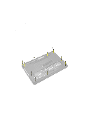
Installing the Input/Output (I/O) Board
1.
Place the I/O board in its slot.
2.
Tighten the screw to secure the I/O board to the computer.
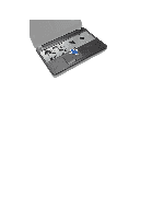
3.
Connect the I/O cable to the system board.
4.
Install:
a)
palmrest
b)
keyboard
c)
access panel
d)
battery
5.
Follow the procedures in
After Working Inside Your Computer
.
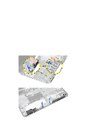
Removing the System Board
1.
Follow the procedures in
Before Working Inside Your Computer
.
2.
Remove:
a)
SD card
b)
battery
c)
access panel
d)
memory module
e)
hard drive
f)
optical drive
g)
keyboard
h)
palmrest
i)
WLAN card
3.
Disconnect the following cables:
a)
display cable
b)
power-connector port cable
c)
speaker cable
d)
I/O board cable
e)
Touch cable (for touch computer only)
21