Dell Latitude E6400 ATG Service Manual - Page 26
Display Assembly - camera
 |
View all Dell Latitude E6400 ATG manuals
Add to My Manuals
Save this manual to your list of manuals |
Page 26 highlights
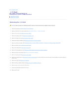
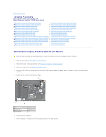
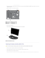
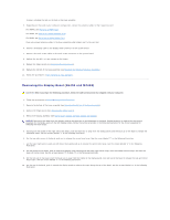
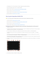
Back to Contents Page Display Assembly Dell™ Latitude™ E6400 and E6400 ATG and Mobile Workstation Precision™ M2400 Service Manual Removing the Display Assembly (E6400 and M2400) Replacing the Display Assembly (E6400 and M2400) Removing the Display Assembly (E6400 ATG) Replacing the Display Assembly (E6400 ATG) Removing the Display Bezel (E6400 and M2400) Replacing the Display Bezel (E6400 and M2400) Removing the Display Bezel (E6400 ATG) Replacing the Display Bezel (E6400 ATG) Removing the CCFL Display Panel and Brackets (E6400 and M2400) Replacing the CCFL Display Panel and Brackets (E6400 and M2400) Removing the LED Display Panel and Brackets (E6400 and M2400) Replacing the LED Display Panel and Brackets (E6400 and M2400) Removing the Display Panel and Brackets (E6400 ATG) Replacing the Display Panel and Brackets (E6400 ATG) Removing the Display Inverter (E6400 and M2400) Replacing the Display Inverter (E6400 and M2400) Removing the Display Hinges (E6400 and M2400) Replacing the Display Hinges (E6400 and M2400) Removing the Display Hinges (E6400 ATG) Replacing the Display Hinges (E6400 ATG) Removing the Microphone Board Replacing the Microphone Board Removing the Camera and Microphone Assembly Replacing the Camera and Microphone Assembly Removing the Latch Hook Assembly Replacing the Latch Hook Assembly Removing the Display Cover Replacing the Display Cover Removing the Display Assembly (E6400 and M2400) CAUTION: Before you begin the following procedure, follow the safety instructions that shipped with your computer. 1. Follow the instructions in Before Working on Your Computer. 2. Remove the bottom of the base assembly (see Removing the Bottom of the Base Assembly). 3. Remove the hinge covers (see Removing the Hinge Covers). 4. Disconnect and unroute the display cable and the wireless cables (WLAN, WWAN, and WPAN). Position all cables to the rear of the laptop after unrouting. 5. Remove the M2.5 x 5-mm screw from each hinge. 1 M2.5 x 5-mm screws (2) 2 display cable 3 WPAN cable 4 WLAN cable 5 WWAN cable 6. Turn the computer topside up. 7. Open the display to 90 degrees and lift the display assembly off the base assembly.
-
 1
1 -
2
-
3
-
4
-
5
-
6
-
7
-
8
-
9
-
10
-
11
-
12
-
13
-
14
-
15
-
16
-
17
-
18
-
19
-
20
-
 21
21 -
 22
22 -
 23
23 -
 24
24 -
 25
25 -
 26
26 -
 27
27 -
 28
28 -
 29
29 -
 30
30 -
 31
31 -
32
-
33
-
34
-
35
-
36
-
37
-
38
-
39
-
40
-
41
-
42
-
43
-
44
-
45
-
46
-
47
-
48
-
49
-
50
-
51
-
52
-
53
-
54
-
55
-
56
-
57
-
58
-
59
-
60
-
61
-
62
-
63
-
64
-
65
-
66
-
67
-
68
-
69
-
70
-
71
-
72
-
73
-
74
-
75
-
76
-
77
-
78
-
79
-
80
-
81
-
82
-
83
-
84
-
85
-
86
-
87
-
88
-
89
-
90
-
91
-
92
-
93
-
94
-
95
-
96
-
97
-
98
-
99
 |
 |