Dell OptiPlex 5050 Micro Micro Owners Manual - Page 21
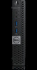
System board layout
 |
View all Dell OptiPlex 5050 Micro manuals
Add to My Manuals
Save this manual to your list of manuals |
Page 21 highlights
System board layout 1 CPU socket connector 3 Internal speaker connector 5 M.2 WLAN connector 7 Hard drive connector 9 Coin cell battery 11 Clear password jumper 13 DP/VGA connector (optional) 2 CPU fan connector 4 Memory module connectors 6 Power switch connector 8 M.2 SSD connector 10 Service Mode Jumper 12 Clear CMOS jumper 14 PS/2 serial connector (optional) Removing and installing components 21
-
 1
1 -
2
-
3
-
4
-
5
-
6
-
7
-
8
-
9
-
10
-
11
-
12
-
13
-
14
-
15
-
 16
16 -
 17
17 -
 18
18 -
 19
19 -
 20
20 -
 21
21 -
 22
22 -
 23
23 -
 24
24 -
 25
25 -
 26
26 -
27
-
28
-
29
-
30
-
31
-
32
-
33
-
34
-
35
-
36
-
37
-
38
-
39
-
40
-
41
-
42
-
43
-
44
-
45
-
46
-
47
-
48
-
49
-
50
-
51
-
52
-
53
-
54
 |
 |

System board layout
1
CPU socket connector
2
CPU fan connector
3
Internal speaker connector
4
Memory module connectors
5
M.2 WLAN connector
6
Power switch connector
7
Hard drive connector
8
M.2 SSD connector
9
Coin cell battery
10
Service Mode Jumper
11
Clear password jumper
12
Clear CMOS jumper
13
DP/VGA connector (optional)
14
PS/2 serial connector (optional)
Removing and installing components
21