Dell OptiPlex G1 Dell OptiPlex G1 Midsize Managed PC Systems Reference and In - Page 113
To remove the insert covering the 3.5-inch bay, To replace the front-panel insert for the 3.5-inch
 |
View all Dell OptiPlex G1 manuals
Add to My Manuals
Save this manual to your list of manuals |
Page 113 highlights
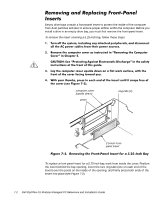
To remove the insert covering the 3.5-inch bay, follow these steps: computer cover (upside down) eject button mechanism To replace the front-panel insert for the 3.5-inch bay, work from outside the cover. Place the insert in position, and press it into the opening. When installing a drive, you connect two cables-a direct current (DC) power cable and an interface cable-to the back of the drive. Your drive's power input connector (to which you connect the DC power cable) resembles the connector shown in Figure 7-4. Installing Drives 7-3
-
 1
1 -
2
-
3
-
4
-
5
-
6
-
7
-
8
-
9
-
10
-
11
-
12
-
13
-
14
-
15
-
16
-
17
-
18
-
19
-
20
-
21
-
22
-
23
-
24
-
25
-
26
-
27
-
28
-
29
-
30
-
31
-
32
-
33
-
34
-
35
-
36
-
37
-
38
-
39
-
40
-
41
-
42
-
43
-
44
-
45
-
46
-
47
-
48
-
49
-
50
-
51
-
52
-
53
-
54
-
55
-
56
-
57
-
58
-
59
-
60
-
61
-
62
-
63
-
64
-
65
-
66
-
67
-
68
-
69
-
70
-
71
-
72
-
73
-
74
-
75
-
76
-
77
-
78
-
79
-
80
-
81
-
82
-
83
-
84
-
85
-
86
-
87
-
88
-
89
-
90
-
91
-
92
-
93
-
94
-
95
-
96
-
97
-
98
-
99
-
100
-
101
-
102
-
103
-
104
-
105
-
106
-
107
-
 108
108 -
 109
109 -
 110
110 -
 111
111 -
 112
112 -
 113
113 -
 114
114 -
 115
115 -
 116
116 -
 117
117 -
 118
118 -
119
-
120
-
121
-
122
-
123
-
124
-
125
-
126
-
127
-
128
-
129
-
130
-
131
-
132
-
133
-
134
-
135
-
136
-
137
-
138
-
139
-
140
-
141
-
142
-
143
-
144
-
145
-
146
-
147
-
148
-
149
-
150
-
151
-
152
-
153
-
154
-
155
-
156
-
157
-
158
-
159
-
160
 |
 |
Installing Drives
7-3
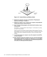
To remove the insert covering the 3.5-inch bay
, follow these steps:
¹·
&RPSOHWH²VWHSV²¹²DQG²º²RI²WKH²SURFHGXUH²IRU²UHPRYLQJ²D²¸·º¸µLQFK²
LQVHUW·
º·
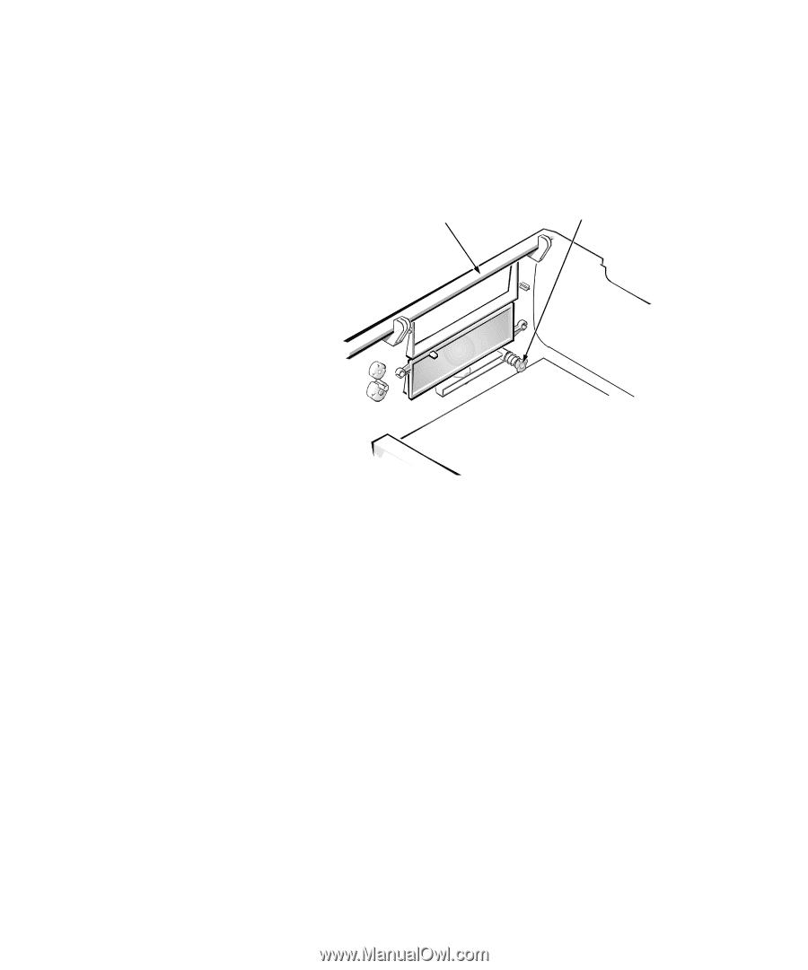
,QVLGH²WKH²FRYHU¶²ORFDWH²WKH²HMHFW²EXWWRQ²PHFKDQLVP²IRU²WKH²»·¸µLQFK²ED\²
³VHH²)LJXUH²¿µ»´·²3UHVV²WKH²PHFKDQLVP²WRZDUG²WKH²IURQW²SDQHO²WR²VQDS²
WKH²SODVWLF²LQVHUW²RXW²RI²LWV²RSHQLQJ·
±
)LJXUH±¼¶¸µ±±5HPRYLQJ±WKH±)URQW¶3DQHO±,QVHUW±IRU±WKH±¸µº¶,QFK±%D\
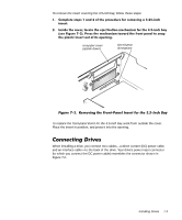
To replace the front-panel insert for the 3.5-inch bay,
work from outside the cover.
Place the insert in position, and press it into the opening.
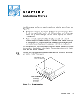
&RQQHFWLQJ±’ULYHV±±±±
When installing a drive, you connect two cables—a direct current (DC) power cable
and an interface cable—to the back of the drive. Your drive’s power input connector
(to which you connect the DC power cable) resembles the connector shown in
Figure 7-4.
computer cover
(upside down)
eject button
mechanism