Dell PowerConnect 2608 User's Guide - Page 9
Connecting Switches to Systems, Class-of-Service - hub
 |
View all Dell PowerConnect 2608 manuals
Add to My Manuals
Save this manual to your list of manuals |
Page 9 highlights
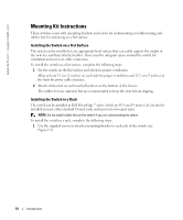
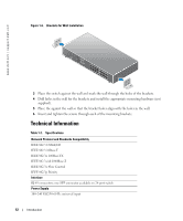
NOTE: Do not connect two switches together with more than one cable. Using multiple cables to connect switches can create a loop and cause collisions. Figure 1-4. Cascading Switches Connecting Switches to Systems By connecting a switch to systems, you can form a small network. To improve network efficiency, use 1000-Mbps full-duplex operation between the server and switch if the LAN adapter on the server can operate in full-duplex mode. All the RJ-45 ports support Auto MDI/MDIX and therefore automatically detect the type of cable used to connect the network device. Crossover or straight-through networking cables can be used to connect PCs as well as other networking devices like hubs or routers to the switch. All ports on the switch automatically negotiate speed and whether to operate in full duplex or half duplex. Class-of-Service The switch supports tag-based prioritization following the IEEE 802.1p standard. The eight levels of IEEE 802.1p priority are mapped to the two priority queues of each port. For each port, the two priority queues are scheduled following a Weighted Round Robin scheme. Table 1-1. Tag-Based Prioritization IEEE 802.1p Priority 0-3 4-7 Priority Queue 0 1 Scheduling Weight 1 2 NOTE: The IEEE 802.1p priority information is part of the IEEE 802.1q tag that also defines VLAN memberships. The switches will ignore the VLAN membership information in the tag (that is, all ports are part of all VLANs), but will preserve the full tag information-including packet priority and VLAN ID- when transmitting the packet at the destination port. Introduction 9
-
 1
1 -
2
-
3
-
 4
4 -
 5
5 -
 6
6 -
 7
7 -
 8
8 -
 9
9 -
 10
10 -
 11
11 -
 12
12 -
 13
13 -
 14
14 -
15
-
16
-
17
-
18
-
19
-
20
-
21
-
22
-
23
-
24
-
25
-
26
-
27
-
28
-
29
-
30
-
31
-
32
-
33
-
34
-
35
-
36
-
37
-
38
 |
 |
