Dell PowerConnect Brocade M5424 Brocade M5424 Blade Server SAN I/O Module Hard - Page 32
Interpreting LED activity
 |
View all Dell PowerConnect Brocade M5424 manuals
Add to My Manuals
Save this manual to your list of manuals |
Page 32 highlights
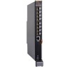
3 Interpreting LED activity Interpreting LED activity Each SAN I/O Module uses LEDs to indicate status. These LEDs are shown in Figure 5. FIGURE 5 LED Locations 1 67 TABLE 4 Location 1 Key to Figure 5 Indicator Color FC (external) green/amber port status 2 (status icon) module and 3 (LED) status green/amber 4 (icons) and 5 module (LED) power green 6 (icon) 7 (LED) server blue/amber management 2 34 5 Operation Note: LED meanings are not valid during boot, diagnostics, or POST. Green: Off (dark): No signal carrier or unlicensed. Steady: Online normal active port but no port activity. Flickering: normal active port (I/O activity). Slow blink: Online but segmented. Fast blink: Internal loopback. Amber Steady: Signal present but not online. Slow blink or flash: Disabled port (less than two second interval). Fast (rapid) blink or flash: Error or fault with port (less than 1/2 second interval). Off: SAN I/O Module is off or power supplies for the Blade Server or onboard DCC have failed. Green: No errors and all ports are ready for use. Amber: Steady: Boot-up state, port(s) offline, or in reset state. Blinking (green/amber): One or more environmental ranges are exceeded, or error log contains diagnostic error messages. Note: The LED might blink during testing. Off: SAN I/O Module is off or power supplies for the Blade Server Enclosure or onboard DCC have failed. Green: Normal operation and power supply is functioning. properly. Power is supplied by the Blade Server Enclosure. Controlled by the Blade Server Enclosure's CMC. For details, refer to the Hardware Owner's Manual for Blade Server Enclosure. 22 M5424 SAN I/O Module Hardware Reference Manual 53-1001082-01
-
 1
1 -
2
-
3
-
4
-
5
-
6
-
7
-
8
-
9
-
10
-
11
-
12
-
13
-
14
-
15
-
16
-
17
-
18
-
19
-
20
-
21
-
22
-
23
-
24
-
25
-
26
-
 27
27 -
 28
28 -
 29
29 -
 30
30 -
 31
31 -
 32
32 -
 33
33 -
 34
34 -
 35
35 -
 36
36 -
 37
37 -
38
-
39
-
40
-
41
-
42
-
43
-
44
-
45
-
46
-
47
-
48
 |
 |
