Dell PowerConnect W-AP175 Dell PowerConnect W-AP175P Installation Guide - Page 7
Outdoor Planning and Deployment Considerations, Scale Requirements - aruba
 |
View all Dell PowerConnect W-AP175 manuals
Add to My Manuals
Save this manual to your list of manuals |
Page 7 highlights
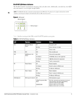
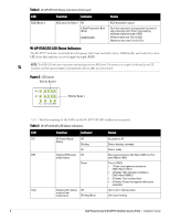
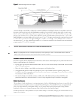
Table 3 W-AP175AC/DC LED Status Indicators (Continued) LED Function Indicator Status ENT R0 R1 RSSI (Radio 0) RSSI (Radio 1) LAN/Network Link Status Off On (Amber) Ethernet link unavailable 10/100 Mbs ethernet link negotiated On (Green) 1000 Mbs ethernet link negotiated Blinking Traffic on ethernet link Radio 0 Status Off Radio 0 disabled On (Amber) Radio 0 enabled in WLAN mode Blinking Air Monitor (AM) mode Radio 1 Status Off Radio 1disabled On (Blue) Radio 1 enabled in WLAN mode Blinking Air Monitor (AM) mode RSSI Level for Radio 0 Off RSSI disabled/no signal 4 Step Progressive Bars (Red) 25/50/75/100% Each bar represents a progressive increase in signal strength, with 4 bars representing maximum signal strength (100%). Minimum data rate: One lit LEDs Maximum data rate: Four lit LEDs RSSI Level for Radio 1 Off RSSI disabled/no signal 4 Step Progressive Bars (Blue) 25/50/75/100% Each bar represents a progressive increase in signal strength, with 4 bars representing maximum signal strength (100%). Minimum data rate: One lit LEDs Maximum data rate: Four lit LEDs Outdoor Planning and Deployment Considerations Prior to deploying an outdoor wireless network, the environment must be evaluated to plan for a successful Dell WLAN deployment. Successfully evaluating the environment enables the proper selection of Dell APs and antennas and assists in the determination of their placement for optimal RF coverage. This process is considered WLAN or RF planning. Scale Requirements The potentially immense scale of outdoor deployments requires consideration of factors that may not be as important in a typical indoor deployment: Range (distance): Range or distance between APs must be taken into account during the planning phase. Available AP mounting locations are often far less flexible in an outdoor environment. Regardless of these outdoor restrictions, the desired goal is to achieve results similar to an indoor deployment: a "dense" RF deployment that supports advanced Aruba features, such as ARM, efficient client roaming, and failover. Elevation: Proper consideration and planning for elevation differences between APs (AP to AP) and AP to Client can be critical to success. To plan for these differences in elevation, it is important to understand the 3D coverage pattern provided by the antennas that will be deployed in the environment. Non-Fixed Considerations: The RF environment might change on a day to day basis. Keep non-fixed items, such as shipping containers, vehicles, and future building construction, in mind when planning for an outdoor deployment. Dell PowerConnect W-AP175 Outdoor Access Point | Installation Guide 7
-
 1
1 -
 2
2 -
 3
3 -
 4
4 -
 5
5 -
 6
6 -
 7
7 -
 8
8 -
 9
9 -
 10
10 -
 11
11 -
 12
12 -
13
-
14
-
15
-
16
-
17
-
18
-
19
-
20
-
21
-
22
-
23
-
24
-
25
-
26
-
27
-
28
-
29
-
30
-
31
-
32
 |
 |
