Dell PowerEdge 2950 Cabling Instructions for the -48 VDC Power Supply - Page 7
Assembling the DC Input Power Cable, CAUTION, NOTICE
 |
View all Dell PowerEdge 2950 manuals
Add to My Manuals
Save this manual to your list of manuals |
Page 7 highlights
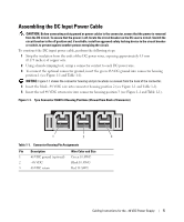
Assembling the DC Input Power Cable CAUTION: Before connecting safety ground or power cables to the connector, ensure that the power is removed from the DC circuit. To ensure that the power is off, locate the circuit breaker on the DC source circuit. Switch the circuit breaker to the off position and, if available, install an approved safety locking device to the circuit breaker or switch, to prevent against another person energizing the circuit. To construct the DC input power cable, perform the following steps: 1 Strip the insulation from the ends of the DC power wires, exposing approximately 4.5 mm (0.175 inches) of copper wire. 2 Using a hand-crimping tool, crimp a connector contact to each DC power wire. 3 To connect the optional connector ground, insert the green 48 VDC ground into connector housing position 1 (see Figure 1-1 and Table 1-1). NOTICE: Figure 1-1 shows the connector housing and pin locations as viewed from the back of the connector. 4 Insert the black -48 VDC wire into connector housing position 2 (see Figure 1-1 and Table 1-1). 5 Insert the red 48 VDC return wire into connector housing position 3 (see Figure 1-1 and Table 1-1). Figure 1-1. Tyco Connector 556879-3 Housing Positions (Viewed from Back of Connector) 1 2 3 Table 1-1. Connector Housing Pin Assignments Pin Description Wire Color and Size 1 48 VDC ground (optional) Green 10 AWG 2 -48 VDC Black 10 AWG 3 48 VDC return Red 10 AWG Cabling Instructions for the -48 VDC Power Supply 5
-
 1
1 -
 2
2 -
 3
3 -
 4
4 -
 5
5 -
 6
6 -
 7
7 -
 8
8 -
 9
9 -
 10
10 -
 11
11 -
 12
12 -
13
-
14
-
15
 |
 |