Dell PowerEdge 4350 Dell PowerEdge Systems Microprocessor Upgrade Guide - Page 17
Removing and Replacing the Guide Brackets
 |
View all Dell PowerEdge 4350 manuals
Add to My Manuals
Save this manual to your list of manuals |
Page 17 highlights
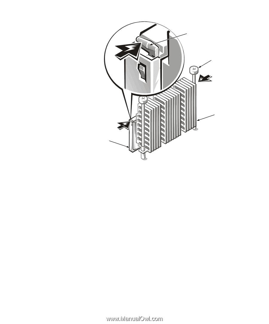
microprocessor release latches (2) thumbscrews (2) heat sink support.dell.com To remove the guide bracket assembly, perform the following steps: 1. Remove any terminator card installed in the guide bracket. 2. Remove any microprocessor assembly installed in the guide bracket. 3. Use a #2 Phillips screwdriver to loosen the four captive nuts that secure the guide bracket assembly to the system board (see Figure 1-5). 4. Lift up the assembly to remove it from the four threaded posts. To install the new guide bracket assembly, perform the following steps: 1. Position the guide bracket over the four threaded posts (see Figure 1-6). You can install the guide bracket only one way (the captive nuts will not align with the threaded posts if installed incorrectly). 2. Tighten the four captive nuts using a #2 Phillips screwdriver. Dell PowerEdge Systems - Microprocessor Upgrade 1-13
-
 1
1 -
2
-
3
-
4
-
5
-
6
-
7
-
8
-
9
-
10
-
11
-
 12
12 -
 13
13 -
 14
14 -
 15
15 -
 16
16 -
 17
17 -
 18
18 -
 19
19 -
 20
20 -
 21
21 -
 22
22 -
23
-
24
 |
 |