Dell PowerEdge M420 Dell 10GbE Pass Through Module (XAUI) User Manual - Page 22
Transmitter Non-Inverted DATA in. AC Coupled.
 |
View all Dell PowerEdge M420 manuals
Add to My Manuals
Save this manual to your list of manuals |
Page 22 highlights
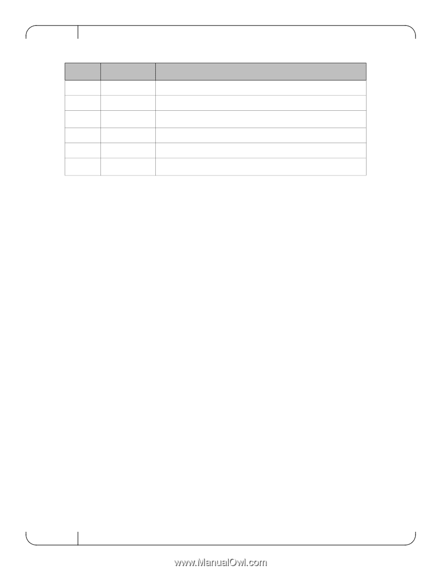
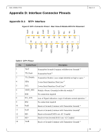
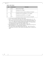
Rev 1.0 Table 8 - SFP+ Pinout Pin Symbol Name Description 15 VccR Receiver Power Supply 16 VccT Transmitter Power Supply 17 VeeT Transmitter Ground (Common with Receiver Ground) a 18 TD+ Transmitter Non-Inverted DATA in. AC Coupled. 19 TD- Transmitter Inverted DATA in. AC Coupled. 20 VeeT Transmitter Ground (Common with Receiver Ground)a a. Circuit ground is internally isolated from chassis ground. b. TFAULT is an open collector/drain output, which should be pulled up with a 4.7k - 10k Ohms resistor on the host board if intended for use. Pull up voltage should be between 2.0V to Vcc + 0.3V. A high output indicates a transmitter fault caused by either the TX bias current or the TX output power exceeding the preset alarm thresholds. A low output indicates normal operation. In the low state, the output is pulled to 2.0V or open, enabled on TDIS
-
 1
1 -
2
-
3
-
4
-
5
-
6
-
7
-
8
-
9
-
10
-
11
-
12
-
13
-
14
-
15
-
16
-
 17
17 -
 18
18 -
 19
19 -
 20
20 -
 21
21 -
 22
22
 |
 |