Dell PowerEdge M420 Brocade M5424 Blade Server SAN I/O Module Hardware Referen - Page 33
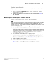
Locating the serial number, Removing and replacing the SAN I/O Module
 |
View all Dell PowerEdge M420 manuals
Add to My Manuals
Save this manual to your list of manuals |
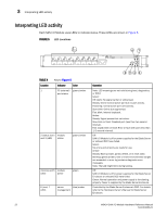
Page 33 highlights
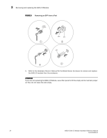
Removing and replacing the SAN I/O Module 3 Locating the serial number Before contacting service support, be sure to obtain the module's serial number. Use one of these methods to locate the number: • Use the CLI and enter the ChassisShow command. The SAN I/O Module serial number is displayed along with other data. • Locate the serial number on the label attached to the SAN I/O Module. Refer to Figure 3 on page 5 for location. Removing and replacing the SAN I/O Module Complete the following steps to remove and replace a failed SAN I/O Module. NOTE Before beginning this procedure, ensure that you have a replacement SAN I/O Module or filler panel available because you do not want to leave the slot on the Blade Server Enclosure open for an extended period of time. The slot must be filled with either a replacement SAN I/O Module or a filler panel to maintain proper airflow. 1. Back up the SAN I/O Module configuration to an FTP server by using the Module's configUpload CLI command and following the prompts. This command uploads the SAN I/O Module configuration to the server, making it available for downloading to a replacement SAN I/O Module if necessary. It is recommended to back up the configuration on a regular basis to ensure that a complete configuration is available for downloading to a replacement SAN I/O Module. 2. Stop all SAN activity requiring the ports used by the SAN I/O Module. For details about port management, refer to your Blade Server Enclosure Hardware Owner's Manual. Verify that there is no activity by viewing the SAN I/O Module LEDs. For details about LED activity on the SAN I/O Module, see "Interpreting LED activity" on page 22. 3. Remove all cables from the SFP modules. 4. Remove the SFP modules according to the manufacturer's instructions. Figure 6 on page 24 details the generic process for removing an SFP from a port. M5424 SAN I/O Module Hardware Reference Manual 23 53-1001082-01
-
 1
1 -
2
-
3
-
4
-
5
-
6
-
7
-
8
-
9
-
10
-
11
-
12
-
13
-
14
-
15
-
16
-
17
-
18
-
19
-
20
-
21
-
22
-
23
-
24
-
25
-
26
-
27
-
 28
28 -
 29
29 -
 30
30 -
 31
31 -
 32
32 -
 33
33 -
 34
34 -
 35
35 -
 36
36 -
 37
37 -
 38
38 -
39
-
40
-
41
-
42
-
43
-
44
-
45
-
46
-
47
-
48
 |
 |