Cable Routing Procedures for Dell™ PowerEdge™ R815 Systems
Page 1
Contents
Introduction
...........................................................................................................................................................
2
Section 1: Cabling a Dell™ PowerEdge™ R815 With a Cable Management Arm (CMA)
.........................
2
1.1
Connecting the CMA Cables to the System
.......................................................................................
2
1.2
Routing the Power Cables Through the Strain Reliefs
......................................................................
3
1.3
Routing the Cables Through the CMA
.................................................................................................
3
1.4
Left-Side Mounting Instructions
...........................................................................................................
3
1.5
Right-Side Mounting Instructions
.........................................................................................................
5
Section 2: Cabling a Dell™ PowerEdge™ R815 System Without a CMA
....................................................
6
2.1
Routing the Cables
..................................................................................................................................
6
2.2
Removing the CMA Brackets for Shallow Racks
................................................................................
6
Section 3: Replacing a Power Supply on a PowerEdge™ R815 System With a CMA
................................
7
3.1
Replacing a Power Supply with a Left-Side Mounted CMA
..............................................................
7
3.2
Replacing a Power Supply with a Right-Side Mounted CMA
...........................................................
7
Table of Figures
Figure 1: System with Cables Installed
..................................................................................................................
2
Figure 2: Routing Power Cables Through the Strain Reliefs
.............................................................................
3
Figure 3: Routing the Cables Through the CMA
.................................................................................................
4
Figure 4: Left-Side Mounted CMA Installation
.....................................................................................................
4
Figure 5: Right-Side Mounted CMA Installation
..................................................................................................
5
Figure 6: Cable Routing Without a CMA
...............................................................................................................
6
Figure 7: Removing the CMA Brackets for Shallow Racks
.................................................................................
6
Figure 8: Replacing the Power Supply
...................................................................................................................
7
 1
1 2
2 3
3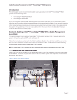 4
4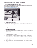 5
5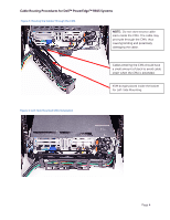 6
6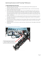 7
7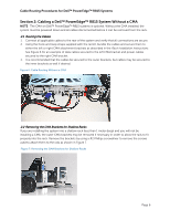 8
8 9
9

