Dell PowerEdge PDU Metered LCD Cabling PowerEdge R415 - Page 11
R415 System Installed in Static Rails
 |
View all Dell PowerEdge PDU Metered LCD manuals
Add to My Manuals
Save this manual to your list of manuals |
Page 11 highlights
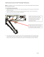
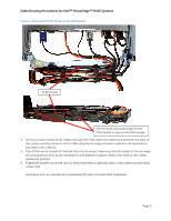
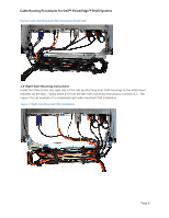
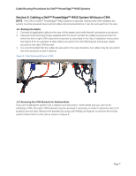
Cable Routing Procedures for Dell™ PowerEdge™ R415 Systems Figure 10: Disconnecting the Inner CMA Attachment Bracket Figure 11: Replacing the Outer Power Supply Disconnected inner CMA bracket Section 4: Cabling a PowerEdge™ R415 System Installed in Static Rails NOTE: The CMA is compatible with the sliding rails only, not the static rails. 1. Follow the instructions contained in the Rack Installation Instructions found in the static rail kit to install the server into a two-post or four-post rack. 2. Install the hook and loop straps provided in the rail kit through the slots in the rear brackets of the rails as described in the Rack Installation Instructions. 3. Connect all applicable cables to the rear of the system and verify that all connections are secure. Page 9
-
 1
1 -
2
-
3
-
4
-
5
-
 6
6 -
 7
7 -
 8
8 -
 9
9 -
 10
10 -
 11
11 -
 12
12
 |
 |
