Cable Routing Procedures for Dell™ PowerEdge™ R310 & R410 Systems
Page 1
Contents
Introduction
...........................................................................................................................................................
2
Section 1: Cabling a Dell™ PowerEdge™ R310 or R410 With a Cable Management Arm (CMA)
..........
2
1.1
Connecting the CMA Cables to the System
.......................................................................................
2
1.2
Installing the Inner CMA Attachment Bracket
....................................................................................
3
1.3
Routing the Power Cables Through the Strain Reliefs
......................................................................
3
1.4
Routing the Cables Through the CMA
.................................................................................................
3
1.5
Left-Side Mounting Instructions
...........................................................................................................
4
1.6
Right-Side Mounting Instructions
.........................................................................................................
6
Section 2: Cabling a Dell™ PowerEdge™ R310 or R410 System Without a CMA
......................................
7
2.1
Routing the Cables
...................................................................................................................................
7
2.2
Removing the CMA Brackets for Shallow Racks
.................................................................................
7
Section 3: Replacing a Power Supply on a PowerEdge™ R310 or R410 System With a CMA
................
8
Section 4: Cabling a PowerEdge™ R310 or R410 System Installed in Static Rails
....................................
9
Table of Figures
Figure 1: System with Cables Installed
...................................................................................................................
2
Figure 2: Attaching the Inner CMA Attachment Bracket
.....................................................................................
3
Figure 3: Routing Power Cables Through the Strain Reliefs
..............................................................................
3
Figure 4: Routing the Cables Through the CMA
..................................................................................................
4
Figure 5: Attaching the KVM Dongle to the CMA Basket
....................................................................................
5
Figure 6: Left-Side Mounted CMA Installation
......................................................................................................
6
Figure 7: Right-Side Mounted CMA Installation
...................................................................................................
6
Figure 8: Cable Routing Without a CMA
................................................................................................................
7
Figure 9: Removing the CMA Brackets for Shallow Racks
..................................................................................
8
Figure 10: Disconnecting the Inner CMA Attachment Bracket
..........................................................................
9
Figure 11: Replacing the Outer Power Supply
......................................................................................................
9
Figure 12: Cabling a System Installed in Static Rails
..........................................................................................
10
 1
1 2
2 3
3 4
4 5
5 6
6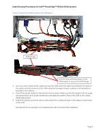 7
7 8
8 9
9

