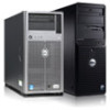
Dell PowerEdge R520 Owner's Manual
Dell PowerEdge R520 Manual
 |
View all Dell PowerEdge R520 manuals
Add to My Manuals
Save this manual to your list of manuals |
Dell PowerEdge R520 manual content summary:
- Dell PowerEdge R520 | Owner's Manual - Page 1
Dell PowerEdge R520 Owner's Manual Regulatory Model: E19S Series Regulatory Type: E19S001 - Dell PowerEdge R520 | Owner's Manual - Page 2
damage to hardware or loss of data and tells you how to avoid the problem. WARNING: A WARNING indicates a Windows®, Windows Server®, Internet Explorer®, MS-DOS®, Windows Vista® and Active Directory® are either trademarks or registered trademarks of Microsoft Corporation in the United States - Dell PowerEdge R520 | Owner's Manual - Page 3
...12 View Menu...12 Hard-Drive Indicator Patterns...13 Back-Panel Features And Indicators...14 NIC Indicator Codes...15 Power Indicator Codes...15 Power Indicator Codes For Non-Redundant Power Supply 17 Other Information You May Need...18 2 Using The System Setup And Boot Manager 19 Choosing The - Dell PowerEdge R520 | Owner's Manual - Page 4
Password Enabled...30 Entering The UEFI Boot Manager...30 Using The Boot Manager Navigation Keys...31 Boot Manager Screen...31 UEFI Boot Menu...32 Embedded System Management...32 iDRAC Settings Utility...32 Entering The iDRAC Settings Utility...32 3 Installing System Components 33 Recommended Tools - Dell PowerEdge R520 | Owner's Manual - Page 5
Installing An AC Power Supply...75 Wiring Instructions For A DC Power Supply...75 Removing A DC Power Supply...78 Installing A DC Power Supply...79 Removing The Power Supply Blank...79 Installing The Power Supply Blank...80 Removing The Power-Distribution And Power-Interposer Boards 80 Installing - Dell PowerEdge R520 | Owner's Manual - Page 6
102 Troubleshooting Power Supplies...102 Troubleshooting Cooling Problems...102 Troubleshooting Cooling Fans...103 Troubleshooting System Memory...103 Troubleshooting An Internal USB Key...104 Troubleshooting An SD Card...104 Troubleshooting An Optical Drive...105 Troubleshooting A Hard Drive...105 - Dell PowerEdge R520 | Owner's Manual - Page 7
109 Running The Embedded System Diagnostics 109 System Diagnostic Controls...110 6 Jumpers And Connectors...111 System Board Jumper Settings...111 System Board Connectors...112 Disabling A Forgotten Password...113 7 Technical Specifications...115 8 System Messages...119 LCD Messages...119 Viewing - Dell PowerEdge R520 | Owner's Manual - Page 8
8 - Dell PowerEdge R520 | Owner's Manual - Page 9
button controls the power supply output to the system. NOTE: On ACPI-compliant operating systems, turning off the system using the power button causes the system to perform a graceful shutdown before power to the system is turned off. 2 NMI button Used to troubleshoot software and device driver - Dell PowerEdge R520 | Owner's Manual - Page 10
to enter BIOS progress mode. To reset the iDRAC (if not disabled in F2 iDRAC setup) press and hold for more than 15 seconds. 4 Video connector Connects a VGA display to the system. 5 LCD menu buttons 6 LCD panel 7 USB connectors (2) 8 Information tag 9 Hard drives (8) Allows you - Dell PowerEdge R520 | Owner's Manual - Page 11
• The LCD backlight remains off if LCD messaging is turned off through the iDRAC utility, the LCD panel, or other tools. Figure 3. LCD Panel Features Item to repeat the cycle Home Screen The Home screen displays user-configurable information about the system. This screen is displayed during normal - Dell PowerEdge R520 | Owner's Manual - Page 12
for iDRAC, iSCSI, or Network devices. Name Displays the name of the Host, Model, or User String for the system Number Displays the Asset tag or the Service tag for the system. Power Displays the power output of the system in BTU/hr or Watts. The display format can be configured in the Set home - Dell PowerEdge R520 | Owner's Manual - Page 13
-Drive Indicators 1. hard-drive activity indicator (green) 2. hard-drive status indicator (green and amber) NOTE: If the hard drive is in Advanced Host Controller Interface (AHCI) mode, the status indicator (on the right side) does not function and remains off. Drive-Status Indicator Pattern (RAID - Dell PowerEdge R520 | Owner's Manual - Page 14
Redundant Power Supply Unit Chassis Item Indicator, Button, or Icon Description Connector 1 PCIe expansion card slot 1 Connects a PCI Express expansion card. 2 vFlash media card slot (Optional) Allows you to insert a vFlash media card. 3 iDRAC port (Optional) Dedicated management port - Dell PowerEdge R520 | Owner's Manual - Page 15
seconds to enter BIOS progress mode. To reset the iDRAC (if not disabled in System Setup) press and hold for more than 15 seconds. 11 Power supply AC 495 W, data is being sent or received. Power Indicator Codes Each AC power supply has an illuminated translucent handle and each DC power supply - Dell PowerEdge R520 | Owner's Manual - Page 16
source is connected to the power supply and that the power supply is operational. Indicates a problem with the power supply. CAUTION: When correcting a power supply mismatch, replace only the power supply with the flashing indicator. Swapping the opposite power supply to make a matched pair can - Dell PowerEdge R520 | Owner's Manual - Page 17
is mismatched with the other power supply (in terms of efficiency, feature set, health status, and supported voltage). Replace the power supply that has the flashing indicator with a power supply that matches the capacity of the other installed power supply. Power Indicator Codes For Non-Redundant - Dell PowerEdge R520 | Owner's Manual - Page 18
. • The Getting Started Guide provides an overview of setting up your system, and technical specifications. This document is available online at support.dell.com/manuals. • The rack documentation included with your rack solution describes how to install your system into a rack, if required. • Any - Dell PowerEdge R520 | Owner's Manual - Page 19
updates, and platform configuration, using a graphical user interface. The exact LC2 feature set is determined by the iDRAC license purchased. For more information, see the Dell LC2 documentation. Enters the BIOS Boot Manager or the Unified Extensible Firmware Interface (UEFI) Boot Manager - Dell PowerEdge R520 | Owner's Manual - Page 20
NOTE: Operating systems must be UEFI-compatible to be installed from the UEFI boot mode. DOS and 32-bit operating systems do not support UEFI and can only be installed from the BIOS boot mode. NOTE: For the latest information on supported operating systems, go to dell.com/ossupport. Entering System - Dell PowerEdge R520 | Owner's Manual - Page 21
related features and options. System Profile Settings Displays options to change the processor power management settings, memory frequency, and so on. System Security Displays options to configure the system security settings like, system password, setup password, TPM security, and so on. It also - Dell PowerEdge R520 | Owner's Manual - Page 22
is Enabled, memory interleaving is supported if a symmetric memory configuration is installed. If Disabled, the system supports Non-Uniform Memory architecture (NUMA) (asymmetric) memory configurations. By default, Node Interleaving option is set to Disabled. Processor Settings Screen Menu Item - Dell PowerEdge R520 | Owner's Manual - Page 23
Allows you to enable or disable Data Cache Unit IP prefetcher. By default, the DCU IP Prefetcher option is set to Enabled. Execute Disable Allows you enable or disable execute disable memory protection technology. By default, the Execute Disable option is set to Enabled. Number of Cores per - Dell PowerEdge R520 | Owner's Manual - Page 24
if the boot mode is BIOS. Allows you to enable or disable UEFI Boot options. NOTE: This option is enabled only if the boot mode is UEFI. Allows you to enable or disable a one-time boot from a selected device. Integrated Devices Screen Menu Item Integrated RAID Controller User Accessible USB Ports - Dell PowerEdge R520 | Owner's Manual - Page 25
of the SD card fails, data is written to the active SD card. Data from this card is copied to the replacement SD card at the next boot. By default, Internal SD Card Redundancy option is set to Mirror. NOTE: This option is displayed only if IDSDM is installed on the system board. Embedded NIC1 and - Dell PowerEdge R520 | Owner's Manual - Page 26
set to Custom. CPU Power Management Allows you to set the CPU power management. By default, the CPU Power Management option is set to System DBPM (DAPC). DBPM is Demand-Based Power Management. Memory Frequency Allows you to set the memory frequency. By default, the Memory Frequency option is set - Dell PowerEdge R520 | Owner's Manual - Page 27
Update Control Allows you to update the BIOS using either DOS or UEFI shell-based flash utilities. For environments that do not require local BIOS updates, it is recommended to set this field to Disabled. By default, the BIOS Update Control option is set to Unlocked. NOTE: BIOS updates using Dell - Dell PowerEdge R520 | Owner's Manual - Page 28
password that you must enter to access and make changes to the BIOS or UEFI settings of your system. CAUTION: The password features provide a basic level of security for the data on your system. CAUTION: Anyone can access the data stored on your system if the system is running and unattended. NOTE - Dell PowerEdge R520 | Owner's Manual - Page 29
Existing System And/Or Setup Password Ensure that the Password jumper is set to enabled and the Password Status is Unlocked before attempting to power-on or reboot. 2. In the System Setup Main Menu, select System BIOS and press . The System BIOS screen is displayed. 3. In the System BIOS - Dell PowerEdge R520 | Owner's Manual - Page 30
and must be powered down. Even UEFI Boot Manager NOTE: Operating systems must be 64-bit UEFI-compatible (for example, Microsoft Windows Server 2008 x64 version) to be installed from the UEFI boot mode. DOS and 32-bit operating systems can only be installed from the BIOS boot mode. The Boot Manager - Dell PowerEdge R520 | Owner's Manual - Page 31
>. The UEFI Boot Menu enables you to Add Boot Option, Delete Boot Option, or Boot From File. Displays a list of the drivers installed on the system and their health status. Enables you to access the System Setup. Enables you to access the BIOS Update File Explorer, run the Dell Diagnostics program - Dell PowerEdge R520 | Owner's Manual - Page 32
Enterprise License upgrade. For more information on using iDRAC, see the iDRAC7 User's Guide under Software → Systems Management → Dell Remote Access Controllers, at support.dell.com/manuals. Entering The iDRAC Settings Utility 1. Turn on or restart the managed system. 2. Press during Power-on - Dell PowerEdge R520 | Owner's Manual - Page 33
required for assembling cables for a DC power supply unit (PSU), when Installing The Front Bezel 1. Hook the right end of the bezel onto the chassis. 2. Fit the free end of the bezel onto the system. 3. Secure the bezel with the keylock. Figure 11. Installing and Removing the Front Bezel 1. release - Dell PowerEdge R520 | Owner's Manual - Page 34
only perform troubleshooting and simple repairs as authorized in your product documentation, or as directed by the online or telephone service and support team. Damage due to servicing that is not authorized by Dell is not covered by your warranty. Read and follow the safety instructions that came - Dell PowerEdge R520 | Owner's Manual - Page 35
only perform troubleshooting and simple repairs as authorized in your product documentation, or as directed by the online or telephone service and support team. Damage due to servicing that is not authorized by Dell is not covered by your warranty. Read and follow the safety instructions that came - Dell PowerEdge R520 | Owner's Manual - Page 36
card 6. expansion-card latch 7. expansion-card riser 1 8. heat sink for processor 1 9. DIMMs (12) 10. cooling fans (6) 11. optical drive (optional) 12. hard drives (8) 13. information tag 14. control-panel board 15. hard-drive backplane 16. power-distribution board 17. power-interposer board 36 - Dell PowerEdge R520 | Owner's Manual - Page 37
3. power supply (non-redundant) 4. expansion-card riser 2 5. expansion card 6. expansion-card latch 7. expansion-card riser 1 8. heat sink for processor 1 9. DIMMs (12) 10. cooling fans (6) 11. optical drive (optional) 12. hard drives (8) 13. information tag 14. control-panel board 15. hard-drive - Dell PowerEdge R520 | Owner's Manual - Page 38
only perform troubleshooting and simple repairs as authorized in your product documentation, or as directed by the online or telephone service and support team. Damage due to servicing that is not authorized by Dell is not covered by your warranty. Read and follow the safety instructions that came - Dell PowerEdge R520 | Owner's Manual - Page 39
or telephone service and support team. Damage due to servicing that is not authorized by Dell is not covered by your warranty. Read and follow the safety instructions that came with the product. NOTE: For proper seating of the cooling shroud in the system chassis, ensure that the cables inside the - Dell PowerEdge R520 | Owner's Manual - Page 40
set is organized into three channels. In each channel, the release levers of the first socket is marked white and the second black. NOTE: DIMMs in sockets A1 to A6 are assigned to processor 1 and DIMMs in sockets B1 to B6 are assigned to processor 2. Figure 16. Memory Socket Locations Memory - Dell PowerEdge R520 | Owner's Manual - Page 41
quad-rank DIMMs in the sockets with white release tabs and dual-rank DIMMs in the sockets with black release tabs. • In a dual-processor configuration, the memory configuration for each processor must be identical. For example, if you populate socket A1 for processor 1, then populate socket B1 for - Dell PowerEdge R520 | Owner's Manual - Page 42
black release tabs. For example, DIMMs installed in sockets A2 and A3 must be identical. Sample Memory Configurations The following tables show sample memory configurations that follow the appropriate memory guidelines stated in this section. NOTE: 16 GB quad-rank RDIMMs are not supported. NOTE - Dell PowerEdge R520 | Owner's Manual - Page 43
, 1600 MT/s 2R x4, 1333 MT/s 2R x4, 1600 MT/s DIMM Slot Population A1, A2 A1, A2, A3, A4, A5 A1, A2, A3 A1, A2, A3, A4, A5 A1, A2, A3 A1, A2, A3, A4 A1, A2, A3 A1, A2, A3, A4, A5, A6 Table 2. Memory Configurations - Two Processor System Capacity (in DIMM Size (in GB) GB) Number of DIMMs - Dell PowerEdge R520 | Owner's Manual - Page 44
only perform troubleshooting and simple repairs as authorized in your product documentation, or as directed by the online or telephone service and support team. Damage due to servicing that is not authorized by Dell is not covered by your warranty. Read and follow the safety instructions that came - Dell PowerEdge R520 | Owner's Manual - Page 45
may not be installed properly. Repeat step 4 through step 7 of this procedure, checking to ensure that the memory modules are firmly seated in their sockets. 14. Run the appropriate diagnostic test. For more information, see Using System Diagnostics. Hard Drives Your system supports: • up to eight - Dell PowerEdge R520 | Owner's Manual - Page 46
are supplied in hot-swappable hard-drive carriers that fit in the hard-drive slots. CAUTION: Before attempting to remove or install a hard drive while the system is running, see the documentation for the storage controller card to ensure that the host adapter is configured correctly to support hot - Dell PowerEdge R520 | Owner's Manual - Page 47
19. Hard-Drive Blank Installation Sequence Removing A Dual Slot Hard-Drive Blank CAUTION: To maintain proper system cooling, all empty hard-drive slots must have hard-drive blanks installed. NOTE: Systems configured for software RAID support only four hard drives. The remaining hard-drive slots are - Dell PowerEdge R520 | Owner's Manual - Page 48
release tabs click into place. 3. If applicable, install the front bezel. Removing A Hot-Swap Hard Drive CAUTION: To prevent data loss, ensure that your operating system supports hot-swap drive installation. See the documentation supplied with your operating system. 1. From the management software - Dell PowerEdge R520 | Owner's Manual - Page 49
. CAUTION: To prevent data loss, ensure that your operating system supports hot-swap drive installation. See the documentation supplied with your operating system. CAUTION: When a replacement hot-swappable hard drive is installed and the system is powered on, the hard drive automatically begins to - Dell PowerEdge R520 | Owner's Manual - Page 50
and support team. Damage due to servicing that is not authorized by Dell is not covered by your warranty. Read and follow the safety instructions that came with the product. 1. Align the screw holes on the 2.5 inch hard drive with the screw holes on the 3.5 inch hard-drive adapter. 2. Install the - Dell PowerEdge R520 | Owner's Manual - Page 51
Figure 23. Removing and Installing a Hot-Swap Hard Drive Into a Hard-Drive Carrier 1. hard-drive carrier 2. screws (4) 3. hard drive 4. screw holes (4) 51 - Dell PowerEdge R520 | Owner's Manual - Page 52
by Dell is not covered by your warranty. Read and follow the safety instructions that came with the product. 1. Insert the hard-drive adapter into the hard-drive carrier with the connector end of the hard drive toward the back. 2. Align the screw holes on the hard drive with the back set of - Dell PowerEdge R520 | Owner's Manual - Page 53
routing of the power/data cable on the side on the system as you remove them from the system board and drive. You must route these cables properly when you replace them to prevent them from being pinched or crimped. 5. To remove the optical drive, press down and push the blue release tab toward the - Dell PowerEdge R520 | Owner's Manual - Page 54
. 3. Remove the fan cable connector from the system board by pressing the tab on the cable end connector, and lifting it away from the system board. 4. Free the cable from the cable holders on the fan bracket. 5. Press the release tab on the cooling fan and lift the fan away from the chassis. 54 - Dell PowerEdge R520 | Owner's Manual - Page 55
and Installing a Cooling Fan 1. cooling fans (6) 2. cooling fan release tab 3. cooling fan cable connector 4. cooling fan connector on the system board Installing A Cooling Fan CAUTION: Many repairs may only be done by a certified service technician. You should only perform troubleshooting and - Dell PowerEdge R520 | Owner's Manual - Page 56
specify the USB memory key in the boot sequence in the System Setup. NOTE: The internal USB connector is located on the expansion-card riser 2. Replacing the Internal USB Key CAUTION: Many repairs may only be done by a certified service technician. You should only perform troubleshooting and simple - Dell PowerEdge R520 | Owner's Manual - Page 57
2. USB memory key Expansion Cards And Expansion-Card Risers NOTE: A missing or an unsupported expansion-card riser logs an SEL event. It does not prevent your system from powering on and no BIOS POST message or F1/F2 pause is displayed. Expansion-Card Installation Guidelines Your system supports - Dell PowerEdge R520 | Owner's Manual - Page 58
only perform troubleshooting and simple repairs as authorized in your product documentation, or as directed by the online or telephone service and support team. Damage due to servicing that is not authorized by Dell is not covered by your warranty. Read and follow the safety instructions that came - Dell PowerEdge R520 | Owner's Manual - Page 59
Figure 28. Removing and Installing the Expansion Card from Expansion-Card Riser 1 1. expansion card 2. expansion-card latch 3. riser 1 59 - Dell PowerEdge R520 | Owner's Manual - Page 60
only perform troubleshooting and simple repairs as authorized in your product documentation, or as directed by the online or telephone service and support team. Damage due to servicing that is not authorized by Dell is not covered by your warranty. Read and follow the safety instructions that came - Dell PowerEdge R520 | Owner's Manual - Page 61
only perform troubleshooting and simple repairs as authorized in your product documentation, or as directed by the online or telephone service and support team. Damage due to servicing that is not authorized by Dell is not covered by your warranty. Read and follow the safety instructions that came - Dell PowerEdge R520 | Owner's Manual - Page 62
only perform troubleshooting and simple repairs as authorized in your product documentation, or as directed by the online or telephone service and support team. Damage due to servicing that is not authorized by Dell is not covered by your warranty. Read and follow the safety instructions that came - Dell PowerEdge R520 | Owner's Manual - Page 63
only perform troubleshooting and simple repairs as authorized in your product documentation, or as directed by the online or telephone service and support team. Damage due to servicing that is not authorized by Dell is not covered by your warranty. Read and follow the safety instructions that came - Dell PowerEdge R520 | Owner's Manual - Page 64
or telephone service and support team. Damage due to servicing that is not authorized by Dell is not covered by your warranty. Read and follow the safety instructions that came with the product. 1. Unpack the iDRAC Ports card and prepare it for installation. For instructions, see the documentation - Dell PowerEdge R520 | Owner's Manual - Page 65
allows automation of server configuration, scripts, and imaging. It emulates USB device(s). For more information, see the iDRAC7 User's Guide at support.dell.com/ manuals. Replacing An SD vFlash Card 1. Locate the vFlash media slot on the iDRAC Ports card. 2. To remove the installed SD vFlash card - Dell PowerEdge R520 | Owner's Manual - Page 66
only perform troubleshooting and simple repairs as authorized in your product documentation, or as directed by the online or telephone service and support team. Damage due to servicing that is not authorized by Dell is not covered by your warranty. Read and follow the safety instructions that came - Dell PowerEdge R520 | Owner's Manual - Page 67
the system. 3. Locate the connector on the system board. 4. Align the connectors on the system board and the dual SD module. 5. Holding the tab, push the dual SD module until it is firmly seated on the system board. NOTE: An L-shaped flange extended from the power supply unit cage supports the dual - Dell PowerEdge R520 | Owner's Manual - Page 68
you to set up the hard drives in RAID configurations as supported by the version of the storage controller included with your system. Removing The Integrated Storage Controller CAUTION: Many repairs may only be done by a certified service technician. You should only perform troubleshooting and - Dell PowerEdge R520 | Owner's Manual - Page 69
on the system board 2. touch-points (2) 3. storage-controller card 4. storage-controller card holder 5. release levers (2) Installing The Integrated Storage Controller CAUTION: Many repairs may only be done by a certified service technician. You should only perform troubleshooting and simple repairs - Dell PowerEdge R520 | Owner's Manual - Page 70
your system, download the latest system BIOS version from support.dell.com and follow the instructions included in the compressed download file to install the update on your system. NOTE: You can update the system BIOS using the Lifecycle Controller. 2. Turn off the system, including any attached - Dell PowerEdge R520 | Owner's Manual - Page 71
Figure 36. Removing and Installing the Heat Sink 1. retention sockets (4) 2. heat sink 3. retention screws (4) CAUTION: The processor is held in its socket under strong pressure. Be aware that the release lever can spring up suddenly if not firmly grasped. 8. Position your thumb firmly over the - Dell PowerEdge R520 | Owner's Manual - Page 72
slot • install a cooling fan in the FAN6 slot • upgrade both the expansion-card risers (riser 1 and riser 2) 1. Before upgrading your system, download the latest system BIOS version from support.dell.com and follow the instructions included in the compressed download file to install the update on - Dell PowerEdge R520 | Owner's Manual - Page 73
new system configuration. 21. Run the system diagnostics to verify that the new processor operates correctly. Power Supplies Your system supports: • Two 495 W, 750 W, or 1100 W AC power supply modules • One cabled power supply module 550 W (non-redundant) • Two 1100 W DC power supply modules (when - Dell PowerEdge R520 | Owner's Manual - Page 74
cable management arm, see the system's rack documentation. 1. Disconnect the power cable from the power source and the power supply you intend to remove and remove the cables from the strap. 2. Press the release latch and slide the power supply out of the chassis. Figure 38. Removing and Installing - Dell PowerEdge R520 | Owner's Manual - Page 75
chassis until the power supply is fully seated and the release latch snaps into place. NOTE: If you unlatched the cable management arm, re-latch it. For information about the cable management arm, see the system's rack documentation. 4. Connect the power cable to the power supply and plug the cable - Dell PowerEdge R520 | Owner's Manual - Page 76
attempt connecting to DC power or installing grounds yourself. All electrical wiring must comply with applicable local or national codes and practices. Damage due to servicing that is not authorized by Dell is not covered by your warranty. Read and follow all safety instructions that came with the - Dell PowerEdge R520 | Owner's Manual - Page 77
or national codes and practices. Damage due to servicing that is not authorized by Dell is not covered by your warranty. Read and follow all safety instructions that came with the product. 1. Strip the insulation from the ends of the DC power wires, exposing approximately 13 mm (0.5 inch) of copper - Dell PowerEdge R520 | Owner's Manual - Page 78
the cable management arm, see the system's rack documentation. 1. Disconnect the power wires from the power source and the connector from the power supply you intend to remove. 2. Disconnect the safety ground wire. 3. Press the release latch and slide the power supply out of the chassis. Figure - Dell PowerEdge R520 | Owner's Manual - Page 79
the chassis until the power supply is fully seated and the release latch snaps into place. NOTE: If you unlatched the cable management arm, re-latch it. For information about the cable management arm, see the system's rack documentation. 4. Connect the safety ground wire. 5. Install the DC power - Dell PowerEdge R520 | Owner's Manual - Page 80
, align the blank with the power supply bay and insert it into the chassis until it clicks into place. Removing The Power-Distribution And Power-Interposer Boards CAUTION: Many repairs may only be done by a certified service technician. You should only perform troubleshooting and simple repairs as - Dell PowerEdge R520 | Owner's Manual - Page 81
Figure 43. Removing and Installing the Power-Distribution Board 1. power-distribution board 2. fan 6 cable connector 3. screws (4) 4. power-interposer board 5. release tab 6. power-distribution board connector 81 - Dell PowerEdge R520 | Owner's Manual - Page 82
Figure 44. Power-Distribution Board Connectors 1. fan 6 cable connector 2. power-distribution board connector 3. 8-pin power connector 82 - Dell PowerEdge R520 | Owner's Manual - Page 83
the four screws that secure the power-distribution board to the chassis. 6. Connect the power-distribution cables to the system board, the fan cable to the power-distribution board, and the power cable to the power-interposer board. 7. Install the power supplies in the system. 8. Close the system - Dell PowerEdge R520 | Owner's Manual - Page 84
telephone service and support team. Damage due to servicing that is not authorized by Dell is not covered by your warranty. Read and follow the safety instructions that came with the product. NOTE: You may have to unlatch and lift the optional cable management arm if it interferes with power supply - Dell PowerEdge R520 | Owner's Manual - Page 85
supply unit cage 3. power supply 4. standoff on the chassis 5. power cable (24 pins) 6. power cable (8 pins) 7. hard-drive backplane power cable Installing A Non-Redundant Power Supply CAUTION: Many repairs may only be done by a certified service technician. You should only perform troubleshooting - Dell PowerEdge R520 | Owner's Manual - Page 86
to secure the power supply to the standoff on the chassis. 5. Connect the power cable to the power supply. 6. Connect the power distribution cables to the system board, and the hard-drive backplane. NOTE: Route the hard-drive backplane power cable through the FAN1 slot's fan blank. 7. Close the - Dell PowerEdge R520 | Owner's Manual - Page 87
unit cage Installing The Redundant Power Supply Unit Divider CAUTION: Many repairs may only be done by a certified service technician. You should only perform troubleshooting and simple repairs as authorized in your product documentation, or as directed by the online or telephone service and support - Dell PowerEdge R520 | Owner's Manual - Page 88
the redundant power supply unit divider to the power supply unit cage. 7. Install the redundant power supplies in the system. 8. Connect the power-distribution cables to the system board, the fan cable to the power-distribution board, and the power cable to the power-interposer board. 9. Close the - Dell PowerEdge R520 | Owner's Manual - Page 89
can replace them in the same locations. 4. Remove all hard drives. 5. Disconnect the SAS/SATA/SSD data cable(s) and power cable from the hard-drive backplane. 6. Disconnect the power/data cable from the control panel board. 7. Press the hard-drive backplane blue release tabs in the direction of the - Dell PowerEdge R520 | Owner's Manual - Page 90
Figure 49. Removing and Installing the Hard-Drive Backplane 1. securing hooks 2. securing slot 3. release tabs (2) 4. SAS A connector 5. backplane signal connector 6. backplane power connector 7. SAS B connector 8. hard-drive backplane 9. hard-drive connectors (8) 90 - Dell PowerEdge R520 | Owner's Manual - Page 91
Figure 50. Cabling Diagram of the Hard-Drive Backplane for a Redundant PSU System 1. system board 2. hard-drive backplane 3. SAS B cable connector 4. power cable connector 5. signal cable connector 6. SAS A cable connector 7. cable routing guide 8. power distribution board 9. cable retention latch - Dell PowerEdge R520 | Owner's Manual - Page 92
the release tabs snap into place. 3. Attach the SAS A cable to the SAS A connector, and the SAS B cable to the SAS B connector on the hard-drive backplane. 4. Connect the power cable(s) to the hard-drive backplane. 5. Route the power/data cables along the chassis wall. 6. Install the hard drives in - Dell PowerEdge R520 | Owner's Manual - Page 93
screwdriver, remove the two screws that secure the control-panel board to the chassis. 6. Slide the control-panel board toward the back and lift it out of the system. Figure 52. Removing and Installing the Control-Panel Board 1. control-panel board 2. screws (2) 3. control-panel data cable 93 - Dell PowerEdge R520 | Owner's Manual - Page 94
4. USB cable Installing The Control-Panel Board CAUTION: Many repairs may only be done by a certified service technician. You should only perform troubleshooting and simple repairs as authorized in your product documentation, or as directed by the online or telephone service and support team. Damage - Dell PowerEdge R520 | Owner's Manual - Page 95
directed by the online or telephone service and support team. Damage due to servicing that is not authorized by Dell is not covered by your warranty. Read and follow the safety instructions that came with the product. 1. Slide the left side of the control panel into the chassis so that the left tab - Dell PowerEdge R520 | Owner's Manual - Page 96
to create and safely store this recovery key. If you replace this system board, you must supply the recovery key when you restart your system or program before you can access the encrypted data on your hard drives. 1. Turn off the system, including any attached peripherals, and disconnect the system - Dell PowerEdge R520 | Owner's Manual - Page 97
components. Figure 53. Removing and Installing the System Board 1. release screws (9) 2. system board holder 3. system board Installing The System Board CAUTION: Many repairs may only be done by a certified service technician. You should only perform troubleshooting and simple repairs as authorized - Dell PowerEdge R520 | Owner's Manual - Page 98
storage controller card c) expansion-card risers d) power supply(s) e) memory modules f) cooling shroud g) If installed, full length expansion card on slot 2 of expansion-card riser 2 6. Connect the cables to the system board. 7. Route the power/data cables through the cable retention bracket - Dell PowerEdge R520 | Owner's Manual - Page 99
to servicing that is not authorized by Dell is not covered by your warranty. Read and follow the safety instructions that came with the product. Troubleshooting System Startup Failure If you boot the system to the BIOS boot mode after installing an operating system from the UEFI Boot Manager, the - Dell PowerEdge R520 | Owner's Manual - Page 100
your system and restore the BIOS to the default settings. 9. Reconnect and power on each USB device one at a time. 10. If a device causes the same problem, power down the device, replace the USB cable with a known good cable, and power up the device. If all troubleshooting fails, see Getting Help - Dell PowerEdge R520 | Owner's Manual - Page 101
are properly installed: - Cooling shroud - Expansion-card risers (if present) - Expansion cards - Power supply(s) - Cooling-fan assembly (if present) - Cooling fans - Processor(s) and heat sink(s) - Memory modules - Hard-drive carriers - Hard-drive backplane 4. Ensure that all cables are properly - Dell PowerEdge R520 | Owner's Manual - Page 102
or telephone service and support team. Damage due to servicing that is not authorized by Dell is not covered by your warranty. Read and follow the safety instructions that came with the product. 1. Reseat the power supply by removing and reinstalling it. NOTE: After installing a power supply, allow - Dell PowerEdge R520 | Owner's Manual - Page 103
support team. Damage due to servicing that is not authorized by Dell is not covered by your warranty. Read and follow the safety instructions that came with the product. 1. Open the system. 2. Reseat the fan or the fan's power cable. 3. If the fan functions properly, close the system. If the problem - Dell PowerEdge R520 | Owner's Manual - Page 104
step 15 for each memory module installed. If the problem persists after all memory modules have been checked, see Getting Help. Troubleshooting An Internal USB Key CAUTION: Many repairs may only be done by a certified service technician. You should only perform troubleshooting and simple repairs as - Dell PowerEdge R520 | Owner's Manual - Page 105
that the hard drive(s) have been configured correctly for the RAID array. c) Take the hard drive offline and reseat the drive. d) Exit the configuration utility and allow the system to boot to the operating system. 3. Ensure that the required device drivers for your controller card are installed and - Dell PowerEdge R520 | Owner's Manual - Page 106
by the online or telephone service and support team. Damage due to servicing that is not authorized by Dell is not covered by your warranty. Read and follow the safety instructions that came with the product. NOTE: When troubleshooting a SAS or PERC controller, also see the documentation for - Dell PowerEdge R520 | Owner's Manual - Page 107
only perform troubleshooting and simple repairs as authorized in your product documentation, or as directed by the online or telephone service and support team. Damage due to servicing that is not authorized by Dell is not covered by your warranty. Read and follow the safety instructions that came - Dell PowerEdge R520 | Owner's Manual - Page 108
108 - Dell PowerEdge R520 | Owner's Manual - Page 109
, see the Dell Online PowerEdge Diagnostics User's Guide under Software → Serviceability Tools, at support.dell.com/manuals. Dell Embedded System Diagnostics NOTE: Also known as Enhanced Pre-boot System Assessment (ePSA) diagnostics. The embedded system diagnostics provides a set of options for - Dell PowerEdge R520 | Owner's Manual - Page 110
all tests run on the system. This is displayed if at least one event description is recorded. For information about embedded system diagnostics, see the Dell Enhanced Pre-boot System Assessment User Guide at support.dell.com/manuals. 110 - Dell PowerEdge R520 | Owner's Manual - Page 111
Board Jumper Settings Jumper Setting Description PWRD_EN (default) The password feature is enabled (pins 2-4). The password feature is disabled (pins 4-6). iDRAC local access is unlocked at the next AC power cycle. NVRAM_CLR (default) The configuration settings are retained at system boot - Dell PowerEdge R520 | Owner's Manual - Page 112
Figure 54. System Board Connectors and Jumpers Item Connector 1 INT_STORAGE 2 ID_BTN 3 CMA_JACK 4 USB 2 5 USB 1 6 IO_RISER2 7 NIC2 8 NIC1 9 VGA 10 COM 11 BATTERY 12 IO_RISER1 13 CPU2 14 FAN6 112 Description Storage controller card connector System identification - Dell PowerEdge R520 | Owner's Manual - Page 113
sockets Cooling fan connector Cooling fan connector 8-pin power connector Cooling fan connector Memory module sockets Backplane signal connector 24-pin power connector Processor socket 1 Power distribution board connector SATA connector A to D Control panel interface connector Optical drive SATA - Dell PowerEdge R520 | Owner's Manual - Page 114
7. Open the system. 8. Move the jumper on the system-board jumper from pins 2 and 4 to pins 4 and 6. 9. Close the system. 10. Reconnect the system to its electrical outlet and turn the system on, including any attached peripherals. 11. Assign a new system and/or setup password. 114 - Dell PowerEdge R520 | Owner's Manual - Page 115
7 Technical Specifications Processor Processor type Expansion Bus install a second processor, you must: • remove the dummy fan from the FAN6 slot • install a cooling fan in the FAN6 slot • upgrade both the expansion-card risers (riser 1 and riser 2) Memory Architecture Memory module sockets Memory - Dell PowerEdge R520 | Owner's Manual - Page 116
Memory Minimum RAM Maximum RAM Drives Hard drives Optical drive Connectors Back NIC Serial USB Video iDRAC7 (Optional) External vFlash card (Optional) Front USB Video Internal USB Internal Dual SD Module (IDSDM) Video Video type Video memory 116 2 GB (single processor configuration) 192 GB Up to - Dell PowerEdge R520 | Owner's Manual - Page 117
environmental measurements for specific system configurations, see dell.com/environmental_datasheets. Standard Operating degrade. • Non-redundant power supplies are not supported. • Non Dell qualified peripheral cards and/or peripheral cards are not supported. Storage Temperature -40 °C - Dell PowerEdge R520 | Owner's Manual - Page 118
118 - Dell PowerEdge R520 | Owner's Manual - Page 119
the SEL and configuring system management settings, see the systems management software documentation. NOTE: If your system fails to boot, press the System as temperature, voltage, fans, and so on, the LCD message is automatically removed when that sensor returns to a normal state. For other faults, - Dell PowerEdge R520 | Owner's Manual - Page 120
board current is outside of the optimum range. Action 1. Review system power policy. 2. Check system logs for power related failures. 3. Review system configuration the system. Details The operating system or an application failed to communicate within the time-out period. The system was - Dell PowerEdge R520 | Owner's Manual - Page 121
CPU configuration is unsupported. Check CPU or BIOS revision. System is unable to boot or may run in a degraded state. Review the technical specifications for supported processor types. CPU0010 Message Details Action CPU is throttled. The CPU is throttled due to thermal or power - Dell PowerEdge R520 | Owner's Manual - Page 122
system. 4. If the issue persists, see Getting Help. CPU0700 Message LCD Message Details Action CPU initialization error detected. CPU initialization error detected. Power cycle system. System BIOS was unable to initialize the processor. 1. Turn off the system and remove input - Dell PowerEdge R520 | Owner's Manual - Page 123
CPU0703 Message CPU bus initialization error detected. LCD Message CPU bus initialization error detected. Power cycle Fan RPM is less than the lower critical threshold. Fan RPM is outside of range. Check fan. Fan operating speed is out of range. Remove and reinstall the fan - Dell PowerEdge R520 | Owner's Manual - Page 124
, see Getting Help. MEM0007 Message Unsupported memory configuration; check memory device at location . LCD Message Unsupported memory configuration. Check memory . Details The memory may not be seated correctly, misconfigured, or has failed. Memory size is reduced. 124 - Dell PowerEdge R520 | Owner's Manual - Page 125
redundancy is lost. Check memory device at location(s) . LCD Message Memory mirror lost on . Power cycle system. Details The memory may not be seated correctly, misconfigured, or has failed. Action Check the memory configuration. Re-seat the memory modules. If the issue - Dell PowerEdge R520 | Owner's Manual - Page 126
be degraded, or system may fail to operate. Action Cycle input power, update component drivers, if device is removable, reinstall the device. PDR0001 Message LCD Message Details Fault detected on drive . Fault detected on drive . Check drive. The controller detected a failure on - Dell PowerEdge R520 | Owner's Manual - Page 127
not configurable. Check memory devices. Details System BIOS detected memory, but was unable to configure the memory for system operation. Action Compare system memory installation to supported system memory configurations. PSU0001 Message LCD Message Action Power supply failed. PSU - Dell PowerEdge R520 | Owner's Manual - Page 128
and power rating. Install matched power supplies and review proper configuration in this manual. PSU0016 Message LCD Message Details Action Power supply is absent. PSU is absent. Check PSU. The power supply has been removed or has failed. 1. Remove and reinstall the power supply - Dell PowerEdge R520 | Owner's Manual - Page 129
the same input type and power rating. Action Install matched power supplies and review this manual for proper configuration. PSU1201 Message Power supply redundancy is lost. Details The power supply tries to operate in a degraded state. System Performance and power redundancy may be degraded - Dell PowerEdge R520 | Owner's Manual - Page 130
log for power supply failures. Review system configuration and power consumption and upgrade or install power supplies accordingly. PWR1005 Message The system performance degraded because the user-defined power capacity has changed. Details The user-defined power settings have affected system - Dell PowerEdge R520 | Owner's Manual - Page 131
event log. Details If the system event log fails to initialize, platform status and failure events are not captured. Some management software do not report platform exceptions. Action Reboot the management controller or iDRAC. Cycle system input power. If problem persists call support. 131 - Dell PowerEdge R520 | Owner's Manual - Page 132
System board voltage is outside of range. Details System hardware detected an over voltage or under voltage condition. If multiple voltage exceptions occur consecutively the system may power down in failsafe mode. Action 1. Review system logs for power supply exceptions. 2. Re-configure the - Dell PowerEdge R520 | Owner's Manual - Page 133
Warning Messages A warning message alerts you to a possible problem and prompts you to respond before the system continues a task. For example, before you format a hard drive, a message warns you that you may lose all data on the hard drive. Warning messages usually interrupt the task and require - Dell PowerEdge R520 | Owner's Manual - Page 134
134 - Dell PowerEdge R520 | Owner's Manual - Page 135
may not be available in your area. To contact Dell for sales, technical support, or customer service issues: 1. Visit support.dell.com. 2. Select your support category. 3. If you are not a U.S. customer, select your country code at the bottom of the support.dell.com page, or select All to see more
-
 1
1 -
 2
2 -
 3
3 -
 4
4 -
 5
5 -
 6
6 -
 7
7 -
8
-
9
-
10
-
11
-
12
-
13
-
14
-
15
-
16
-
17
-
18
-
19
-
20
-
21
-
22
-
23
-
24
-
25
-
26
-
27
-
28
-
29
-
30
-
31
-
32
-
33
-
34
-
35
-
36
-
37
-
38
-
39
-
40
-
41
-
42
-
43
-
44
-
45
-
46
-
47
-
48
-
49
-
50
-
51
-
52
-
53
-
54
-
55
-
56
-
57
-
58
-
59
-
60
-
61
-
62
-
63
-
64
-
65
-
66
-
67
-
68
-
69
-
70
-
71
-
72
-
73
-
74
-
75
-
76
-
77
-
78
-
79
-
80
-
81
-
82
-
83
-
84
-
85
-
86
-
87
-
88
-
89
-
90
-
91
-
92
-
93
-
94
-
95
-
96
-
97
-
98
-
99
-
100
-
101
-
102
-
103
-
104
-
105
-
106
-
107
-
108
-
109
-
110
-
111
-
112
-
113
-
114
-
115
-
116
-
117
-
118
-
119
-
120
-
121
-
122
-
123
-
124
-
125
-
126
-
127
-
128
-
129
-
130
-
131
-
132
-
133
-
134
-
135
 |
 |

Dell PowerEdge R520
Owner's Manual
Regulatory Model: E19S Series
Regulatory Type: E19S001