Dell PowerEdge R520 Owner's Manual - Page 72
Installing A Processor, Removing and Installing a Processor
 |
View all Dell PowerEdge R520 manuals
Add to My Manuals
Save this manual to your list of manuals |
Page 72 highlights
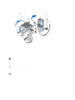
Figure 37. Removing and Installing a Processor 1. processor 2. processor shield 3. notches in processor (4) 4. socket keys (4) 5. ZIF socket 6. socket-release lever NOTE: After removing the processor, place it in an antistatic container for reuse, return, or temporary storage. Do not touch the bottom of the processor. Touch only the side edges of the processor. Installing A Processor CAUTION: Many repairs may only be done by a certified service technician. You should only perform troubleshooting and simple repairs as authorized in your product documentation, or as directed by the online or telephone service and support team. Damage due to servicing that is not authorized by Dell is not covered by your warranty. Read and follow the safety instructions that came with the product. NOTE: If you install a second processor, you must: • remove the dummy fan from the FAN6 slot • install a cooling fan in the FAN6 slot • upgrade both the expansion-card risers (riser 1 and riser 2) 1. Before upgrading your system, download the latest system BIOS version from support.dell.com and follow the instructions included in the compressed download file to install the update on your system. 72
-
 1
1 -
2
-
3
-
4
-
5
-
6
-
7
-
8
-
9
-
10
-
11
-
12
-
13
-
14
-
15
-
16
-
17
-
18
-
19
-
20
-
21
-
22
-
23
-
24
-
25
-
26
-
27
-
28
-
29
-
30
-
31
-
32
-
33
-
34
-
35
-
36
-
37
-
38
-
39
-
40
-
41
-
42
-
43
-
44
-
45
-
46
-
47
-
48
-
49
-
50
-
51
-
52
-
53
-
54
-
55
-
56
-
57
-
58
-
59
-
60
-
61
-
62
-
63
-
64
-
65
-
66
-
 67
67 -
 68
68 -
 69
69 -
 70
70 -
 71
71 -
 72
72 -
 73
73 -
 74
74 -
 75
75 -
 76
76 -
 77
77 -
78
-
79
-
80
-
81
-
82
-
83
-
84
-
85
-
86
-
87
-
88
-
89
-
90
-
91
-
92
-
93
-
94
-
95
-
96
-
97
-
98
-
99
-
100
-
101
-
102
-
103
-
104
-
105
-
106
-
107
-
108
-
109
-
110
-
111
-
112
-
113
-
114
-
115
-
116
-
117
-
118
-
119
-
120
-
121
-
122
-
123
-
124
-
125
-
126
-
127
-
128
-
129
-
130
-
131
-
132
-
133
-
134
-
135
 |
 |
