Dell PowerEdge R610 Hardware Owner's Manual
Dell PowerEdge R610 Manual
 |
View all Dell PowerEdge R610 manuals
Add to My Manuals
Save this manual to your list of manuals |
Dell PowerEdge R610 manual content summary:
- Dell PowerEdge R610 | Hardware Owner's Manual - Page 1
Dell™ PowerEdge™ R610 Systems Hardware Owner's Manual - Dell PowerEdge R610 | Hardware Owner's Manual - Page 2
indicates potential damage to hardware or loss of data if instructions are not followed. WARNING: A WARNING indicates a potential Dell Inc. is strictly forbidden. Trademarks used in this text: Dell, the DELL logo, and PowerEdge are trademarks of Dell Inc.; Intel is a registered trademark of Intel - Dell PowerEdge R610 | Hardware Owner's Manual - Page 3
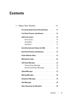
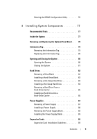
Your System 11 Accessing System Features During Startup 11 Front-Panel Features and Indicators 12 LCD Panel Features 14 Home Screen 15 Setup Menu 16 View Menu 16 Hard-Drive Indicator Patterns for RAID 17 Back-Panel Features and Indicators 19 Power Indicator Codes 21 NIC Indicator Codes 22 - Dell PowerEdge R610 | Hardware Owner's Manual - Page 4
the UEFI Boot Manager 70 Using the UEFI Boot Manager Navigation Keys . . 70 UEFI Boot Manager Screen 71 UEFI Boot Settings Screen 71 System Utilities Screen 72 System and Setup Password Features 72 Using the System Password 72 Using the Setup Password 74 iDRAC Configuration Utility 76 - Dell PowerEdge R610 | Hardware Owner's Manual - Page 5
Hot-Swap Hard Drive 84 Removing a Hard Drive From a Hard-Drive Carrier 85 Installing a Hard Drive Into a Hard-Drive Carrier 85 Power Supplies 87 Removing a Power Supply 87 Installing a Power Supply 88 Removing the Power Supply Blank 89 Installing the Power Supply Blank 89 Expansion Cards 89 - Dell PowerEdge R610 | Hardware Owner's Manual - Page 6
95 Removing the Internal SD Module Card 97 Internal SD Flash Card 97 Installing an Internal SD Flash Card 97 Removing an Internal SD Flash Card 98 Internal USB Memory Key 98 Internal USB Cable 99 Removing the Internal USB Cable 99 Installing the Internal USB Cable 100 VFlash Media 100 - Dell PowerEdge R610 | Hardware Owner's Manual - Page 7
the Integrated Storage Controller Card 112 RAID Battery 114 Removing a RAID Battery 114 Installing a RAID Battery 114 Removing the PERC 6/I Battery Cable 114 Installing the PERC 6/I Battery Cable 115 System Memory 116 General Memory Module Installation Guidelines 116 Mode-Specific Guidelines - Dell PowerEdge R610 | Hardware Owner's Manual - Page 8
142 Troubleshooting a USB Device 142 Troubleshooting a Serial I/O Device 143 Troubleshooting a NIC 143 Troubleshooting a Wet System 144 Troubleshooting a Damaged System 145 Troubleshooting the System Battery 146 Troubleshooting Power Supplies 146 Troubleshooting System Cooling Problems 147 - Dell PowerEdge R610 | Hardware Owner's Manual - Page 9
151 Troubleshooting Hard Drives 152 Troubleshooting a SAS Controller 153 Troubleshooting an External Tape Drive 154 Troubleshooting Expansion Cards 155 Troubleshooting the Processors 157 5 Running the System Diagnostics 159 Using Dell™ PowerEdge™ Diagnostics 159 System Diagnostics Features - Dell PowerEdge R610 | Hardware Owner's Manual - Page 10
7 Getting Help 167 Contacting Dell 167 Glossary 169 Index 179 10 Contents - Dell PowerEdge R610 | Hardware Owner's Manual - Page 11
to select a boot device. Boot Mode set to UEFI: Enters the UEFI Boot Manager, which enables you to manage your system's boot options. Enters PXE boot (if enabled in System Setup program). - Dell PowerEdge R610 | Hardware Owner's Manual - Page 12
controls the DC power supply output to the system. When the system bezel is installed, the power button is not accessible. NOTE: When powering on the system, the video monitor can take up to 25 seconds to display an image, depending on the amount of memory installed in the system. NOTE: On ACPI - Dell PowerEdge R610 | Hardware Owner's Manual - Page 13
Connector 2 NMI button 3 USB connectors (2) 4 Video connector 5 LCD menu buttons 6 LCD panel 7 System identification button Description Used to troubleshoot software and device driver errors when using certain operating systems. This button can be pressed using the end of a paper clip - Dell PowerEdge R610 | Hardware Owner's Manual - Page 14
drive or DVD+RW drive. NOTE: DVD devices are data only. A slide-out panel for system information including the Express Service tag, embedded NIC MAC address, and iDRAC6 Enterprise card MAC address. Space is provided for an additional label. LCD Panel Features The system's LCD panel provides system - Dell PowerEdge R610 | Hardware Owner's Manual - Page 15
Figure 1-2. LCD Panel Features 1 23 4 Item Buttons 1 Left 2 Select 3 Right 4 System ID Description Moves the cursor back in one-step increments. Selects the menu item highlighted by the cursor. Moves the cursor forward in one-step increments. During message scrolling: • Press once - Dell PowerEdge R610 | Hardware Owner's Manual - Page 16
). Displays the MAC addresses for DRAC, iSCSIn, or NETn. Displays the name of the Host, Model, or User String for the system. Displays the Asset tag or the Service tag for the system. Displays the power output of the system in BTU/hr or Watts. The display format can be configured in the "Set home - Dell PowerEdge R610 | Hardware Owner's Manual - Page 17
in Celsius or Fahrenheit. The display format can be configured in the "Set home" submenu of the Setup menu (see "Setup Menu"). Hard-Drive Indicator Patterns for RAID Figure 1-3. Hard Drive Indicators 1 2 1 drive-activity indicator (green) 2 drive-status indicator (green and amber) About Your - Dell PowerEdge R610 | Hardware Owner's Manual - Page 18
per second Blinks green slowly Steady green Description Identify drive/preparing for removal Drive ready for insertion or removal NOTE: The drive status indicator remains off until all hard drives are initialized after system power is applied. Drives are not ready for insertion or removal during - Dell PowerEdge R610 | Hardware Owner's Manual - Page 19
on the system's back panel. Figure 1-4. Back-Panel Features and Indicators 1 2 3 4 5 6 7 8 9 10 11 12 13 Item Indicator, Button, or Icon Connector 1 iDRAC6 Enterprise port (optional) 2 VFlash media slot (optional) 3 serial connector 4 PCIe slot 1 5 video connector 6 USB connectors - Dell PowerEdge R610 | Hardware Owner's Manual - Page 20
be used to locate a particular system within a rack. When one of these buttons is pushed, the LCD panel on the front and the system status indicator on the chassis back panel light blue until one of the buttons is pushed again. 717-W or 502-W power supply 717-W or 502-W power supply 20 About Your - Dell PowerEdge R610 | Hardware Owner's Manual - Page 21
installed power supply. CAUTION: If troubleshooting a PSU mismatch error, replace only the power supply with the flashing indicator. Swapping the opposite power supply to create a matched pair can result in an error condition and unexpected system shutdown. To change from a High Output configuration - Dell PowerEdge R610 | Hardware Owner's Manual - Page 22
Figure 1-5. Power Supply Status Indicator 1 1 power supply status NIC Indicator Codes Figure 1-6. NIC Indicators 1 2 1 link indicator 2 activity indicator 22 About Your System - Dell PowerEdge R610 | Hardware Owner's Manual - Page 23
Log (SEL). (The messages are shown here in "simple" text format.) For information on the SEL and configuring system management settings, see the systems management software documentation. NOTE: If your system fails to boot, press the System ID button for at least five seconds until an error code - Dell PowerEdge R610 | Hardware Owner's Manual - Page 24
error. Contact support. E1114 Ambient Temp exceeds allowed range. E1116 Memory disabled, temp above range. Power cycle AC. E1210 Motherboard battery failure. Check battery. E1211 RAID Controller battery failure. Check battery. Cause Corrective Actions Check the system event log Remove AC power - Dell PowerEdge R610 | Hardware Owner's Manual - Page 25
failed. Failed. Reseat DIMMs. Reseat the memory modules. See "Troubleshooting System Memory." E122E On-board regulator failed. Call support. One of the on-board voltage regulators failed. Remove AC power to the system for 10 seconds and restart the system. If the problem persists, see "Getting - Dell PowerEdge R610 | Hardware Owner's Manual - Page 26
that the processor exceeding acceptable temperature heat sinks are properly range. Check range. installed. See CPU heatsink. "Troubleshooting the Processors" and "Troubleshooting System Cooling Problems." E1418 CPU # not detected. Check CPU is seated properly. Specified processor is - Dell PowerEdge R610 | Hardware Owner's Manual - Page 27
) Code Text Cause Corrective Actions E141F CPU # protocol error. Power cycle AC. The system BIOS has reported a processor protocol error. Remove AC power to the system for 10 seconds and restart the system. If the problem persists, see "Getting Help." E1420 CPU Bus parity error. Power cycle - Dell PowerEdge R610 | Hardware Owner's Manual - Page 28
supply is Check the AC power attached to the system, but source for the specified it has lost its AC input. power supply. If the problem persists, see "Troubleshooting Power Supplies." E1620 Power Supply # (### W) AC power error. Check PSU cables. Specified power supply's AC input is outside of - Dell PowerEdge R610 | Hardware Owner's Manual - Page 29
the reported a PCI system error PCIe expansion cards. If on a component that the problem persists, see resides in PCI "Troubleshooting configuration space at bus Expansion Cards." ##, device ##, function ##. PCI system error on Slot #. Review & clear SEL. The system BIOS has Reinstall the - Dell PowerEdge R610 | Hardware Owner's Manual - Page 30
bus ##, device ##, function##. Check the SEL for details of the error message and then clear the SEL. Remove AC power to the system for 10 seconds and restart the system. If the problem persists, see "Getting Help." E1717 CPU ## internal error. Review & clear SEL. The system BIOS has determined - Dell PowerEdge R610 | Hardware Owner's Manual - Page 31
component that resides in PCI configuration space at bus ##, device ##, function ##. Remove and reseat the PCIe expansion cards. If the problem persists, see "Troubleshooting Expansion Cards." PCIe fatal error on Slot #. Review & clear SEL. The system BIOS has Reinstall the expansion- reported - Dell PowerEdge R610 | Hardware Owner's Manual - Page 32
Memory configured but unusable. Check DIMMs. Memory configured, but is unusable. See "Troubleshooting System Memory." E2013 BIOS unable to shadow memory. Check DIMMs. The system BIOS failed to copy its flash image into memory. See "Troubleshooting System Memory." E2014 CMOS RAM failure. Power - Dell PowerEdge R610 | Hardware Owner's Manual - Page 33
." E2018 Programmable Timer error. Power cycle AC. Programmable interval timer error. Remove AC power to the system for 10 seconds and restart the system. If the problem persists, see "Getting Help." E2019 Parity error. Parity error. Power cycle AC. Remove AC power to the system for 10 seconds - Dell PowerEdge R610 | Hardware Owner's Manual - Page 34
power to the system for 10 seconds and restart the system. If the problem persists, see "Getting Help." E201E POST memory BIOS POST memory test test failure. failure. Check DIMMs. See "Troubleshooting System Memory." If the problem persists, see "Getting Help." E2020 CPU Processor configuration - Dell PowerEdge R610 | Hardware Owner's Manual - Page 35
(MBE). See "Troubleshooting System Memory." E2111 SBE log disabled on DIMM ##. Reseat DIMM. The system BIOS has Remove AC power to the disabled memory single-bit system for 10 seconds and error (SBE) logging and will restart the system. not log anymore SBEs until If the problem persists, the - Dell PowerEdge R610 | Hardware Owner's Manual - Page 36
problem persists, replace the RAID battery. See "Installing a RAID Battery." W1627 Power required > PSU wattage. Check PSU and config. The system configuration requires more power than what the power supply can provide. Turn off power to the system, reduce the hardware configuration or install - Dell PowerEdge R610 | Hardware Owner's Manual - Page 37
installed in a configuration that supports Advanced ECC Memory Mode. Check other system messages for additional information for possible causes. For memory configuration information, see "System Memory." Check other messages for faulty memory modules. If the problem persists, see "Troubleshooting - Dell PowerEdge R610 | Hardware Owner's Manual - Page 38
than normal to boot. Remove AC power to the system for 10 seconds and restart the system. Alert! Node Interleaving disabled! Memory configuration does not support Node Interleaving. The memory configuration Ensure that the memory does not support node modules are installed in a interleaving - Dell PowerEdge R610 | Hardware Owner's Manual - Page 39
system configuration. Alert! Continuing system boot accepts the risk that system may power down without warning. The system configuration of processor(s), memory modules, and expansion cards may not be supported by the power supplies. If any system components were just upgraded, return the system - Dell PowerEdge R610 | Hardware Owner's Manual - Page 40
) Message Causes Corrective Actions BIOS Update Remote BIOS update Attempt Failed! attempt failed. Retry the BIOS update. If the problem persists, see "Getting Help." Caution! NVRAM_CLR jumper is installed on system board NVRAM_CLR jumper is installed in the clear setting. CMOS has been - Dell PowerEdge R610 | Hardware Owner's Manual - Page 41
and UEFI Boot Manager." Decreasing Faulty or improperly installed Reseat the memory modules. available memory memory modules. See "Troubleshooting System Memory." DIMM configuration on each CPU should match. Invalid memory configuration on a dualprocessor system. The DIMM configuration for - Dell PowerEdge R610 | Hardware Owner's Manual - Page 42
in BIOS. The OS NIC=DISABLED, Management Shared NIC Management interface is enabled in Shared NIC= management tools. ENABLED Check the system management software or the System Setup program for NIC settings. If a problem is indicated, see "Troubleshooting a NIC." Error 8602 Auxiliary Device - Dell PowerEdge R610 | Hardware Owner's Manual - Page 43
of manufacturing mode. Maximum rank count exceeded. The following DIMM has been disabled: x Invalid memory configuration. The system will run but with the specified DIMM disabled. Ensure that the memory modules are installed in a valid configuration. See "System Memory." About Your System 43 - Dell PowerEdge R610 | Hardware Owner's Manual - Page 44
Faulty or improperly installed See "Troubleshooting System memory modules. Memory." Memory Initialization Warning: Memory size may be reduced Invalid memory Ensure that the memory configuration. The system modules are installed in a will run but with less memory valid configuration. See than - Dell PowerEdge R610 | Hardware Owner's Manual - Page 45
boot device available Faulty or missing optical drive subsystem, hard drive, or hard-drive subsystem, or no bootable USB key installed. Use a bootable USB key, CD, or hard drive. If the problem persists, see "Troubleshooting an Internal SD Card," and "Troubleshooting Hard Drives," "Troubleshooting - Dell PowerEdge R610 | Hardware Owner's Manual - Page 46
Configuration Error Error encountered in initializing PCIe device; faulty system board. Install the NVRAM_CLR jumper in the clear position (pins 1 and 3) and reboot the system. See "System Board Connectors" for jumper location. If the problem persists, see "Troubleshooting Expansion Cards." Quad - Dell PowerEdge R610 | Hardware Owner's Manual - Page 47
(s) installed in your system. See "Troubleshooting a USB Device," "Troubleshooting an Internal SD Card," and "Troubleshooting Hard Drives." SATA port x There is no device connected Information only. device not found to the specified SATA port. SATA port x device autosensing error The drive - Dell PowerEdge R610 | Hardware Owner's Manual - Page 48
be faulty. If memory has been added or removed, this message is informative and can be ignored. If memory has not been added or removed, check the SEL to determine if single-bit or multi-bit errors were detected and replace the faulty memory module. See "Troubleshooting System Memory." 48 About - Dell PowerEdge R610 | Hardware Owner's Manual - Page 49
sensor Invalid memory Ensure that the memory not detected on x configuration. A mismatched modules are installed in a DIMM is installed. valid configuration. See "System Memory." Time-of-day clock stopped Faulty battery or faulty chip. See "Troubleshooting the System Battery." Time-of - Dell PowerEdge R610 | Hardware Owner's Manual - Page 50
Unable to launch System Services image. System halted! System halted after Restart the system and keystroke because System update the Unified Server Services image is either Configurator respository to corrupted in the system the latest software to restore firmware, or the system full - Dell PowerEdge R610 | Hardware Owner's Manual - Page 51
See "Troubleshooting System Memory." If the problem persists, see "Getting Help." Unsupported CPU combination Unsupported CPU stepping detected Processor(s) is not supported Install a supported processor by the system. or processor combination. See "Processors." Unsupported DIMM detected. The - Dell PowerEdge R610 | Hardware Owner's Manual - Page 52
See "Installing the Control Panel Display Module." Warning! No micro Micro code update failed. code update loaded for processor n Update the BIOS firmware. See "Getting Help." Warning! Power required exceeds PSU wattage. Check PSU and system configuration. Warning! Performance degraded. CPU and - Dell PowerEdge R610 | Hardware Owner's Manual - Page 53
the memory modules are installed in a valid configuration. See "System Memory." If the problem persists, see "Troubleshooting System Memory." Write fault Write fault on selected drive Faulty USB device, USB Replace the USB medium or medium, optical drive USB device. See assembly, hard drive - Dell PowerEdge R610 | Hardware Owner's Manual - Page 54
to a possible problem and prompts you to respond before the system continues a task system diagnostics. Alert Messages Systems management software generates alert messages for your system. Alert messages include information, status, warning, and failure messages for drive, temperature, fan, and power - Dell PowerEdge R610 | Hardware Owner's Manual - Page 55
how to install your system into a rack. • The Getting Started Guide provides an overview of system features, setting up your system, and technical specifications. • Any media that ships with your system that provides documentation and tools for configuring and managing your system, including those - Dell PowerEdge R610 | Hardware Owner's Manual - Page 56
56 About Your System - Dell PowerEdge R610 | Hardware Owner's Manual - Page 57
the system hardware configuration • Enable or disable integrated devices • Set performance and power management thresholds • Manage system security Choosing the System Boot Mode The System Setup program also enables you to specify the boot mode for installing your operating system: • BIOS boot mode - Dell PowerEdge R610 | Hardware Owner's Manual - Page 58
message appears while the system is booting, make a note of the message. See "System Messages" for an explanation of the message and suggestions for correcting errors. NOTE: After installing a memory upgrade, it is normal for your system to display a message that the system memory size has changed - Dell PowerEdge R610 | Hardware Owner's Manual - Page 59
to installed memory. See "Memory Settings Screen." Processor Settings Displays information related to microprocessors (speed, cache size, and so on). See "Processor Settings Screen." SATA Settings See "SATA Settings Screen." Boot Settings See "Boot Settings Screen." Integrated Devices See - Dell PowerEdge R610 | Hardware Owner's Manual - Page 60
select F1 to continue or F2 to enter the System Setup program. CAUTION: When setting this option to Disabled, the system will not halt if an error occurs during POST. Any critical errors will be displayed and logged in the system event log. 60 Using the System Setup Program and UEFI Boot Manager - Dell PowerEdge R610 | Hardware Owner's Manual - Page 61
the amount of video memory. System Memory Testing Specifies whether system memory tests are run at system (Enabled default) boot. Options are Enabled and Disabled. Memory Operating Mode This field displays the type of memory operation if a valid memory configuration is installed. When set to - Dell PowerEdge R610 | Hardware Owner's Manual - Page 62
(ATA Mode default) Port A (Auto default) Description ATA Mode enables the integrated SATA controller. Off disables the controller. Auto enables BIOS support for the device attached to SATA port A. Off disables BIOS support for the device. 62 Using the System Setup Program and UEFI Boot Manager - Dell PowerEdge R610 | Hardware Owner's Manual - Page 63
SD Card slot. A device installed in the Internal SD Card slot will automatically emulate a hard drive. If you install a device in this slot that is configured as a removable diskette drive, you must manually set the emulation type to Floppy. If this field is enabled and the system has failed to boot - Dell PowerEdge R610 | Hardware Owner's Manual - Page 64
iSCSI Boot, and Disabled. PXE support allows the system to boot from the network. MAC Address Displays the MAC address for the NIC. Capability Detected Displays the features of the NIC hardware key, if installed. NOTE: Some NIC features may require the installation of an additional driver. OS - Dell PowerEdge R610 | Hardware Owner's Manual - Page 65
or disables BIOS support for the integrated video controller. NOTE: Integrated video can only be disabled if a video expansion card is installed. If set to Disabled, virtual KVM and other remote access features will not function. PCI IRQ Assignments Screen Option Description Use - Dell PowerEdge R610 | Hardware Owner's Manual - Page 66
, Custom, or Maximum Performance. If you select OS Control, Active Power Controller, or Maximum Performance, the BIOS preconfigures the remaining options on this screen. If you select Custom, you can configure each option independently. 66 Using the System Setup Program and UEFI Boot Manager - Dell PowerEdge R610 | Hardware Owner's Manual - Page 67
sets the CPU power to System DBPM, the fan power to Minimum Power, and the memory power to Maximum Performance. In this setting, processor performance is controlled by the system BIOS. Maximum Performance sets all fields to Maximum Performance. If you select Custom, you can configure each option - Dell PowerEdge R610 | Hardware Owner's Manual - Page 68
default) Description Displays the current status of the password security feature and allows a new system password assignment and verification. NOTE: See "Using the System Password" for more information. Restricts access to the System Setup program by using a setup password. NOTE: See "Using the - Dell PowerEdge R610 | Hardware Owner's Manual - Page 69
) CAUTION: Clearing the TPM will lose all encryption keys in the TPM. This option prevents booting to the operating system and results in data loss if the encryption keys cannot be restored. Back up the TPM keys prior to enabling this option. Enables or disables the NMI feature. AC Power Recovery - Dell PowerEdge R610 | Hardware Owner's Manual - Page 70
Server® 2008 x64 version) to be installed from the UEFI boot mode. DOS and 32-bit operating systems can only be installed from the BIOS boot mode. NOTE: The Boot Mode must be set to UEFI in the System Setup program to access the UEFI Boot Manager. The UEFI Boot Manager enables you to: • Add, delete - Dell PowerEdge R610 | Hardware Owner's Manual - Page 71
-swap a boot device, press to refresh the list of boot options. Enables you to add, delete, enable, or disable boot options; change boot order; or execute a one-time boot option. Enables you to access the System Setup program, System Services, and BIOS-level boot options. UEFI Boot Settings - Dell PowerEdge R610 | Hardware Owner's Manual - Page 72
Option System Setup System Services BIOS Boot Manager Reboot System Description Accesses the System Setup program without rebooting. Restarts the system and accesses the Unified Server Configurator, which enables you to run utilities such as system diagnostics. Accesses the BIOS-level boot options - Dell PowerEdge R610 | Hardware Owner's Manual - Page 73
from the field without assigning a system password, press to move System Password changes to Enabled. Exit the System Setup program and begin using your system. 6 Either reboot the system system accepts your setup password as an alternate system or reboot your system by pressing - Dell PowerEdge R610 | Hardware Owner's Manual - Page 74
> when prompted at reboot. If an incorrect system password is entered, the system displays a message and prompts you to re- system displays an error message that the system has halted and must be shut down manually using the power button. Even after you shut down and restart the system, the error - Dell PowerEdge R610 | Hardware Owner's Manual - Page 75
press to access the setup password window. Press twice to clear the existing setup password. The setting changes to Not Enabled. 3 If you want to assign a new setup password, perform the steps in "Assigning a Setup Password." Using the System Setup Program and UEFI Boot Manager 75 - Dell PowerEdge R610 | Hardware Owner's Manual - Page 76
card port or the embedded NICs. • Enable or disable IPMI over LAN. • Enable a LAN Platform Event Trap (PET) destination. • Attach or detach the Virtual Media devices. • Change the administrative username and password and manage user privileges. • View System Event Log (SEL) messages or clear - Dell PowerEdge R610 | Hardware Owner's Manual - Page 77
authorized in your product documentation, or as directed by the online or telephone service and support team. Damage due to servicing that is not authorized by Dell is not covered by your warranty. Read and follow the safety instructions that came with the product. Installing System Components 77 - Dell PowerEdge R610 | Hardware Owner's Manual - Page 78
the System 1 12 11 10 9 2 3 4 5 6 7 1 power supply bays (2) 3 iDRAC6 Enterprise card 5 memory modules (12) 7 SAS backplane 9 optical drive 11 Internal SD Module 8 2 expansion-card riser (2) 4 integrated storage controller card 6 heat sink/processor (2) 8 hard drives (6) 10 RAID battery (PERC - Dell PowerEdge R610 | Hardware Owner's Manual - Page 79
then fit the free end of the bezel onto the system. Secure the bezel with the keylock. See Figure 3-2. Information Tag The information tag is a slide-out label panel for system information including the Express Service tag, Embedded NIC1 MAC address, and iDRAC6 Enterprise card MAC address. Removing - Dell PowerEdge R610 | Hardware Owner's Manual - Page 80
only perform troubleshooting and simple repairs as authorized in your product documentation, or as directed by the online or telephone service and support team. Damage due to servicing that is not authorized by Dell is not covered by your warranty. Read and follow the safety instructions that came - Dell PowerEdge R610 | Hardware Owner's Manual - Page 81
hooks on the back edge of the cover fit over the corresponding tabs on the back edge of the chassis. See Figure 3-3. 3 Slide the cover towards the front of the chassis and close the latch. 4 Rotate the latch release lock in a clockwise direction to secure the cover. Installing System Components 81 - Dell PowerEdge R610 | Hardware Owner's Manual - Page 82
that fit in the hard-drive bays. CAUTION: Before attempting to remove or install a drive while the system is running, see the documentation for the integrated storage controller card to ensure that the host adapter is configured correctly to support hot-swap drive removal and insertion. CAUTION - Dell PowerEdge R610 | Hardware Owner's Manual - Page 83
a Hard-Drive Blank 1 2 1 hard-drive blank 2 latch Installing a Hard-Drive Blank Align the hard-drive blank with the drive bay and insert the blank into the drive bay until the release lever clicks into place. Removing a Hot-Swap Hard Drive CAUTION: Ensure that your operating system supports hot - Dell PowerEdge R610 | Hardware Owner's Manual - Page 84
hard drive, ensure that the adjacent drives are fully installed. Inserting a hard-drive carrier and attempting to lock its handle next to a partially installed carrier can damage the partially installed carrier's shield spring and make it unusable. CAUTION: Ensure that your operating system supports - Dell PowerEdge R610 | Hardware Owner's Manual - Page 85
on the hard-drive carrier and separate the hard drive from the carrier. See Figure 3-6. Installing a Hard Drive Into a Hard-Drive Carrier 1 Insert the hard drive into the hard-drive carrier with the connector end of the drive at the back. See Figure 3-6. 2 Align the holes on the hard drive with the - Dell PowerEdge R610 | Hardware Owner's Manual - Page 86
Figure 3-6. Installing a Hard Drive Into a Drive Carrier 3 2 1 1 screws (4) 3 hard drive 4 2 drive carrier 4 SAS screw hole 86 Installing System Components - Dell PowerEdge R610 | Hardware Owner's Manual - Page 87
in the PS1 power supply bay. Removing a Power Supply CAUTION: To ensure proper system cooling, the power supply blank must be installed in power supply bay PS2 in a non-redundant configuration. See "Removing the Power Supply Blank." CAUTION: If troubleshooting a PSU mismatch error, replace only the - Dell PowerEdge R610 | Hardware Owner's Manual - Page 88
3 release latch 2 Velcro strap Installing a Power Supply 1 On a system with redundant power supplies, verify that both power supplies are the same type and have the same maximum output power. NOTE: The maximum output power (shown in watts) is listed on the power supply label. 2 Slide the new - Dell PowerEdge R610 | Hardware Owner's Manual - Page 89
2 expansion cards are supported in both slots. CAUTION: To ensure proper cooling, only one of the two expansion cards can have a power consumption of greater than 15W (up to 25W maximum), not including the integrated storage controller. • Table 3-1 provides a guide for installing expansion cards to - Dell PowerEdge R610 | Hardware Owner's Manual - Page 90
or telephone service and support team. Damage due to servicing that is not authorized by Dell is not covered by your warranty. Read and follow the safety instructions that came with the product. 1 Unpack the expansion card and prepare it for installation. For instructions, see the documentation - Dell PowerEdge R610 | Hardware Owner's Manual - Page 91
c Close the expansion-card latch. See Figure 3-8. Figure 3-8. Installing or Removing an Expansion Card 1 2 3 1 expansion-card latch 3 expansion-card riser 2 expansion card 6 Connect any cables to the expansion card. 7 Close the system. See "Closing the System." Installing System Components 91 - Dell PowerEdge R610 | Hardware Owner's Manual - Page 92
authorized in your product documentation, or as directed by the online or telephone service and support team. Damage due to servicing that is not authorized by Dell is not covered by your warranty. Read and follow the safety instructions that came with the product. 92 Installing System Components - Dell PowerEdge R610 | Hardware Owner's Manual - Page 93
, including any attached peripherals, and disconnect the system from the electrical outlet. 2 Open the system. See "Opening the System." 3 If an expansion card is installed in the expansion slot, remove the card now. See "Removing an Expansion Card." 4 If you are removing the riser 1, remove the - Dell PowerEdge R610 | Hardware Owner's Manual - Page 94
Figure 3-9. Installing or Removing an Expansion-Card Riser 1 2 3 4 5 9 8 6 7 94 Installing System Components - Dell PowerEdge R610 | Hardware Owner's Manual - Page 95
Controller Card." 5 Close the system. See "Closing the System." 6 Reconnect the system and peripherals to their power sources. Internal SD Module Installing the Internal SD Module CAUTION: Many repairs may only be done by a certified service technician. You should only perform troubleshooting and - Dell PowerEdge R610 | Hardware Owner's Manual - Page 96
SD module 8 internal SD flash card 4 Connect the internal SD module cable to the connector on the control panel board. See Figure 3-10. 5 Close the system. See "Closing the System." 6 Reconnect the system and peripherals to their power sources, and turn them on. 96 Installing System Components - Dell PowerEdge R610 | Hardware Owner's Manual - Page 97
service and support team. Damage due to servicing that is not authorized by Dell is not covered by your warranty. Read and follow the safety instructions that came with the product. The optional SD Flash Card on the Internal SD module supports an embedded hypervisor for virtualization. Installing - Dell PowerEdge R610 | Hardware Owner's Manual - Page 98
and remove the card. 4 Close the system. See "Closing the System." 5 Reconnect the system to power and restart the system. Internal USB Memory Key The USB memory key can be used as a boot device, security key, or mass storage device. To use the internal USB connector, the Internal USB Port option - Dell PowerEdge R610 | Hardware Owner's Manual - Page 99
the system to power and restart the system. Figure 3-11. Removing or Installing the Internal USB Memory Key 1 3 2 1 control panel board 3 USB memory key 2 USB memory key connector Internal USB Cable Removing the Internal USB Cable CAUTION: Many repairs may only be done by a certified service - Dell PowerEdge R610 | Hardware Owner's Manual - Page 100
any other cables from the cable routing guides. 6 Remove the USB cable from the connector on the system board. Installing the Internal USB Cable CAUTION: Many repairs may only be done by a certified service technician. You should only perform troubleshooting and simple repairs as authorized in your - Dell PowerEdge R610 | Hardware Owner's Manual - Page 101
Installing a VFlash Media Card 1 Locate the VFlash media slot at the back corner of the system. See "BackPanel Features and Indicators" for the location of the media slot. 2 With the label side facing up, insert the contact-pin end of the SD card into the card slot on the module. NOTE: The slot is - Dell PowerEdge R610 | Hardware Owner's Manual - Page 102
safety instructions that came with the product. 1 Turn off the system, including any attached peripherals, and disconnect the system from the electrical outlet. 2 Disconnect the Ethernet cable from the iDRAC6 Enterprise Card connector on the system back panel. See Figure 1-4. 102 Installing System - Dell PowerEdge R610 | Hardware Owner's Manual - Page 103
card away from the back of the system until the RJ-45 connector is clear of the back panel, then lift the card out of the system. 7 Reinstall the expansion card. See "Installing an Expansion Card." 8 Close the system. See "Closing the System." 9 Reconnect the system and peripherals to their power - Dell PowerEdge R610 | Hardware Owner's Manual - Page 104
a sixth fan (FAN6) is required for dual-processor systems. NOTE: Hot-swap removal or installation of the fans or fan assembly is not supported. NOTE: In the event of a problem with a particular fan, the fan number is referenced by the system's management software, allowing you to easily identify and - Dell PowerEdge R610 | Hardware Owner's Manual - Page 105
only perform troubleshooting and simple repairs as authorized in your product documentation, or as directed by the online or telephone service and support team. Damage due to servicing that is not authorized by Dell is not covered by your warranty. Read and follow the safety instructions that came - Dell PowerEdge R610 | Hardware Owner's Manual - Page 106
only perform troubleshooting and simple repairs as authorized in your product documentation, or as directed by the online or telephone service and support team. Damage due to servicing that is not authorized by Dell is not covered by your warranty. Read and follow the safety instructions that came - Dell PowerEdge R610 | Hardware Owner's Manual - Page 107
FAN4 6 FAN6 (dual-processor configurations only) 8 fan power connectors (6) 10 fan blank (must be installed in single processor configuration for proper cooling airflow) Replacing . 2 Connect each fan's power cable to the power connectors on the system board. Installing System Components 107 - Dell PowerEdge R610 | Hardware Owner's Manual - Page 108
system. See "Closing the System." 7 Reconnect the system and peripherals to their power sources, and turn them on. Optical Drive An optional slimline DVD or DVD-RW optical drive slides into the front panel and connects to the SATA controller on the system board. 108 Installing System Components - Dell PowerEdge R610 | Hardware Owner's Manual - Page 109
only perform troubleshooting and simple repairs as authorized in your product documentation, or as directed by the online or telephone service and support team. Damage due to servicing that is not authorized by Dell is not covered by your warranty. Read and follow the safety instructions that came - Dell PowerEdge R610 | Hardware Owner's Manual - Page 110
only perform troubleshooting and simple repairs as authorized in your product documentation, or as directed by the online or telephone service and support team. Damage due to servicing that is not authorized by Dell is not covered by your warranty. Read and follow the safety instructions that came - Dell PowerEdge R610 | Hardware Owner's Manual - Page 111
battery cable from a PERC card can cause data loss if the "dirty cache" LED on the card is lit. The LED indicates that data is still cached in controller memory and the data was not cleared at system shutdown. 5 Remove the card from the storage controller card slot: Installing System Components - Dell PowerEdge R610 | Hardware Owner's Manual - Page 112
only perform troubleshooting and simple repairs as authorized in your product documentation, or as directed by the online or telephone service and support team. Damage due to servicing that is not authorized by Dell is not covered by your warranty. Read and follow the safety instructions that came - Dell PowerEdge R610 | Hardware Owner's Manual - Page 113
cable connector 3 back card edge guide (black) 5 front card edge guide (blue) 7 SAS data cable 2 integrated storage controller card 4 expansion card riser 1 6 RAID battery connector (PERC only) 8 cable retention clip 5 Close the system. See "Closing the System." Installing System Components 113 - Dell PowerEdge R610 | Hardware Owner's Manual - Page 114
The information in this section applies only to systems with the optional battery-cached PERC controller card. CAUTION: Many repairs may only be done by a certified service technician. You should only perform troubleshooting and simple repairs as authorized in your product documentation, or as - Dell PowerEdge R610 | Hardware Owner's Manual - Page 115
7 Remove the fan cable from the plastic cable routing guide. It might be necessary to remove other cables from the routing guide. 8 Disconnect the battery cable from the RAID battery. Installing the PERC 6/I Battery Cable 1 Turn off the system, including any attached peripherals, and disconnect the - Dell PowerEdge R610 | Hardware Owner's Manual - Page 116
Memory Module Installation Guidelines To ensure optimal performance of your system, observe the following general guidelines when configuring your system memory. NOTE: Memory configurations that fail to observe these guidelines can prevent your system from starting and producing any video output - Dell PowerEdge R610 | Hardware Owner's Manual - Page 117
. This mode supports Single Device Data Correction (SDDC) for both x4- and x8-based memory modules. Memory modules must be identical in size, speed, and technology in corresponding slots. Memory Mirroring Support The system supports memory mirroring if identical memory modules are installed in the - Dell PowerEdge R610 | Hardware Owner's Manual - Page 118
quad-rank memory-module configurations, nor do they address the memory speed considerations of any configuration. Table 3-2. RDIMM Memory Configurations Memory Mode Memory Module Size Memory Sockets Single Processor 1 2 3 Physical Available 4 5 6 Memory Memory 118 Installing System Components - Dell PowerEdge R610 | Hardware Owner's Manual - Page 119
Available 4 5 6 Memory Memory (GB) (GB) Dual Processor Physical Available Memory Memory (GB) (GB) Optimizer 1-GB X 1 XX 2 XXX 3 XXXX 4 XXXXXX 6 all 2 all 4 6 8 12 2-GB X 2 all 4 all XX 4 8 XXX 6 12 XXXX 8 16 X X X X X X 12 24 Installing System Components 119 - Dell PowerEdge R610 | Hardware Owner's Manual - Page 120
or telephone service and support team. Damage due to servicing that is not authorized by Dell is not covered by your warranty. Read and follow the safety instructions that came with the product. WARNING: The memory modules are hot to the touch for some time after the system has been powered down - Dell PowerEdge R610 | Hardware Owner's Manual - Page 121
Close the system. See "Closing the System." 10 Start up the system, press to enter the System Setup program, and check the System Memory setting on the main System Setup screen. The system should have already changed the value to reflect the newly installed memory. Installing System Components - Dell PowerEdge R610 | Hardware Owner's Manual - Page 122
or telephone service and support team. Damage due to servicing that is not authorized by Dell is not covered by your warranty. Read and follow the safety instructions that came with the product. WARNING: The memory modules are hot to the touch for some time after the system has been powered down - Dell PowerEdge R610 | Hardware Owner's Manual - Page 123
came with the product. 1 Prior to upgrading your system, download and install the latest system BIOS version from support.dell.com. Follow the instructions included in the file download to install the update on your system. 2 Turn off the system, including any attached peripherals, and disconnect - Dell PowerEdge R610 | Hardware Owner's Manual - Page 124
and a heat-sink blank to ensure proper system cooling. Adding the blanks is similar to adding a processor. See "Installing a Processor." NOTE: In single-processor configurations, a processor must be installed in socket CPU1. Install the blanks in socket CPU2 only. 124 Installing System Components - Dell PowerEdge R610 | Hardware Owner's Manual - Page 125
. 1 If you are upgrading your processors, prior to upgrading your system, download and install the latest system BIOS version from support.dell.com. Follow the instructions included in the file download to install the update on your system. NOTE: In single-processor configurations, socket CPU1 must - Dell PowerEdge R610 | Hardware Owner's Manual - Page 126
heatsink blank heat-sink retention latches. See Figure 3-20. 7 Close the system. See "Closing the System." 8 Press to enter the System Setup program, and check that the processor information matches the new system configuration. See "Entering the System Setup Program." 126 Installing System - Dell PowerEdge R610 | Hardware Owner's Manual - Page 127
online or telephone service and support team. Damage due to servicing that is not authorized by Dell is not covered by your warranty. Read and follow the safety instructions that came with the product. WARNING: There is a danger of a new battery exploding if it is incorrectly installed. Replace the - Dell PowerEdge R610 | Hardware Owner's Manual - Page 128
negative side of battery connector 2 system battery 3 Locate the battery socket. See Figure 6-1. CAUTION: To avoid damage to the battery connector, you must firmly support the connector while installing or removing a battery. 4 Remove the system battery. a Support the battery connector by pressing - Dell PowerEdge R610 | Hardware Owner's Manual - Page 129
display module and the control panel circuit board. Use the following instructions to remove and install either module. Removing the Control Panel Display Module CAUTION: Many repairs may only be done by a certified service technician. You should only perform troubleshooting and simple repairs as - Dell PowerEdge R610 | Hardware Owner's Manual - Page 130
panel board 5 USB cable 7 display module 2 display module cable 4 control panel cable 6 mounting screws (3 Torx) 16 Using a T10 Torx driver, remove the two screws that secure the display module to the system chassis. 17 Remove the display module from the chassis cutout. 130 Installing System - Dell PowerEdge R610 | Hardware Owner's Manual - Page 131
panel board. 4 Close the system. See "Closing the System." 5 Reconnect the system to the power source and turn on the system and attached peripherals. Removing the Control Panel Board CAUTION: Many repairs may only be done by a certified service technician. You should only perform troubleshooting - Dell PowerEdge R610 | Hardware Owner's Manual - Page 132
only perform troubleshooting and simple repairs as authorized in your product documentation, or as directed by the online or telephone service and support team. Damage due to servicing that is not authorized by Dell is not covered by your warranty. Read and follow the safety instructions that came - Dell PowerEdge R610 | Hardware Owner's Manual - Page 133
5 Disconnect the power cable from the end of the SAS backplane. 6 Disconnect the SAS data cables from the backplane. 7 Remove the SAS backplane from the system: a While pulling the two blue latches towards the front of the system, slide the backplane upward. See Figure 3-23. b When the backplane - Dell PowerEdge R610 | Hardware Owner's Manual - Page 134
Figure 3-23. Removing and Installing a SAS Backplane 1 2 3 4 1 SAS backplane power cable 3 SAS A cable 5 retention hooks (2) 5 6 2 SAS backplane 4 SAS B cable 6 backplane retention latches (2) 134 Installing System Components - Dell PowerEdge R610 | Hardware Owner's Manual - Page 135
only perform troubleshooting and simple repairs as authorized in your product documentation, or as directed by the online or telephone service and support team. Damage due to servicing that is not authorized by Dell is not covered by your warranty. Read and follow the safety instructions that came - Dell PowerEdge R610 | Hardware Owner's Manual - Page 136
lift the system board assembly by grasping a memory module, processor, or other components. b Grasp the system board assembly by the blue and black storage card guides, or the edges of the system board tray, and lift the assembly from the chassis. See Figure 3-24. 136 Installing System Components - Dell PowerEdge R610 | Hardware Owner's Manual - Page 137
Figure 3-24. Removing and Installing the System Board 1 2 1 retention pin 2 system board assembly Installing System Components 137 - Dell PowerEdge R610 | Hardware Owner's Manual - Page 138
cable, if applicable • Control panel interface cable connector • Optical drive power cable connector • Control panel USB interface cable connector • SAS backplane power cable connector 8 Replace the expansion-card risers. See "Replacing an Expansion-Card Riser." 138 Installing System Components - Dell PowerEdge R610 | Hardware Owner's Manual - Page 139
cables under the guide on the end of riser 1. 11 If applicable, reconnect the RAID battery cable to the PERC controller card. 12 If applicable, reinstall the iDRAC6 Enterprise card. See "Installing an iDRAC6 Enterprise Card." 13 Replace the fan assembly. See "Cooling Fans." 14 Close the system. See - Dell PowerEdge R610 | Hardware Owner's Manual - Page 140
140 Installing System Components - Dell PowerEdge R610 | Hardware Owner's Manual - Page 141
same boot mode in which you installed the operating system. See "Using the System Setup Program and UEFI Boot Manager." • Invalid memory configurations could cause the system to halt at startup without any video output. See "System Memory." For all other startup issues, note the LCD panel messages - Dell PowerEdge R610 | Hardware Owner's Manual - Page 142
, replace the faulty keyboard/mouse. If the problem is not resolved, proceed to the next step to begin troubleshooting the other USB devices attached to the system. 2 Power down all attached USB devices and disconnect them from the system. 3 Reconnect and power on each USB device one at a time. 142 - Dell PowerEdge R610 | Hardware Owner's Manual - Page 143
4 If a device causes the same problem, power down the device, replace the USB cable if applicable, and power up the device. If the problem persists, replace the device. If all troubleshooting fails, see "Getting Help." Troubleshooting a Serial I/O Device 1 Turn off the system, including any attached - Dell PowerEdge R610 | Hardware Owner's Manual - Page 144
from the system. See "Installing System Components." • Hard drives • SD cards • USB memory key • NIC hardware key • Internal SD Module • Expansion cards and both expansion-card risers • Integrated storage controller • iDRAC6 Enterprise card • Power supplies 144 Troubleshooting Your System - Dell PowerEdge R610 | Hardware Owner's Manual - Page 145
, and disconnect the system from the electrical outlet. 2 Open the system. See "Opening the System." 3 Ensure that the following components are properly installed: • Expansion cards and both expansion-card risers • Power supplies • Fans • Processors and heat sinks Troubleshooting Your System 145 - Dell PowerEdge R610 | Hardware Owner's Manual - Page 146
telephone service and support team. Damage due to servicing that is not authorized by Dell is not covered by your warranty. Read and follow the safety instructions that came with the product. If the problem is not resolved by replacing the battery, see "Getting Help." Troubleshooting Power Supplies - Dell PowerEdge R610 | Hardware Owner's Manual - Page 147
that none of the following parts are missing: system cover, drive blank, FAN6 blank (in a system with a single processor), power supply blank (in a system with a single power supply), heat sink blank (in single processor configurations), or front or back filler panel. • Ambient temperature is too - Dell PowerEdge R610 | Hardware Owner's Manual - Page 148
or telephone service and support team. Damage due to servicing that is not authorized by Dell is not covered by your warranty. Read and follow the safety instructions that came with the product. 1 Locate the faulty fan indicated by the LCD panel or the diagnostic software. 2 Turn off the system and - Dell PowerEdge R610 | Hardware Owner's Manual - Page 149
from the power source. 13 Open the system. See "Opening the System." 14 If a diagnostic test or error message indicates a specific memory module as faulty, swap or replace the module. 15 To troubleshoot an unspecified faulty memory module, replace the memory module in the first DIMM socket with - Dell PowerEdge R610 | Hardware Owner's Manual - Page 150
or the LCD panel on the front of the system. 19 If the memory problem is still indicated, repeat step 12 through step 18 for each memory module installed. If the problem persists after all memory modules have been checked, see "Getting Help." Troubleshooting an Internal SD Card CAUTION: Many repairs - Dell PowerEdge R610 | Hardware Owner's Manual - Page 151
or telephone service and support team. Damage due to servicing that is not authorized by Dell is not covered by your warranty. Read and follow the safety instructions that came with the product. 1 Enter the System Setup program and ensure that the USB port is enabled. See "Integrated Devices Screen - Dell PowerEdge R610 | Hardware Owner's Manual - Page 152
telephone service and support team. Damage due to servicing that is not authorized by Dell is not covered by your warranty. Read and follow the safety instructions that came with the product. CAUTION: This troubleshooting procedure can destroy data stored on the hard drive. Before you proceed, back - Dell PowerEdge R610 | Hardware Owner's Manual - Page 153
Take the hard drive offline and then reseat the hard drive. See "Removing a Hot-Swap Hard Drive." d Exit the configuration utility and allow the system to boot to the operating system. 4 Ensure that the required device drivers for your controller card are installed and are configured correctly. See - Dell PowerEdge R610 | Hardware Owner's Manual - Page 154
Opening the System." 7 Ensure that the controller card is firmly seated into the expansion card connector. See "Installing the Integrated Storage Controller Card." 8 If you have a battery-cached PERC controller, ensure that the RAID battery is properly connected and, if applicable, the memory module - Dell PowerEdge R610 | Hardware Owner's Manual - Page 155
outlet, and turn on the system, including attached peripherals. If the problem is not resolved, see the documentation for the tape drive for additional troubleshooting instructions. If you cannot resolve the problem, see "Getting Help." Troubleshooting Expansion Cards CAUTION: Many repairs may only - Dell PowerEdge R610 | Hardware Owner's Manual - Page 156
15 For each expansion card you removed in step 11, perform the following steps: a Turn off the system and attached peripherals, and disconnect the system from the electrical outlet. b Open the system. See "Opening the System." c Reinstall one of the expansion cards. 156 Troubleshooting Your System - Dell PowerEdge R610 | Hardware Owner's Manual - Page 157
only perform troubleshooting and simple repairs as authorized in your product documentation, or as directed by the online or telephone service and support team. Damage due to servicing that is not authorized by Dell is not covered by your warranty. Read and follow the safety instructions that came - Dell PowerEdge R610 | Hardware Owner's Manual - Page 158
outlet. 15 Open the system. See "Closing the System." 16 Replace the processor with the processor you removed in step 10. See "Installing a Processor." 17 Repeat step 11 through step 13. If the problem persists, the system board is faulty. See "Getting Help." 158 Troubleshooting Your System - Dell PowerEdge R610 | Hardware Owner's Manual - Page 159
support.dell.com and on the CDs that came with your system. For information about using diagnostics, see the Dell Online PowerEdge Diagnostics User's Guide. System Diagnostics Features The system diagnostics provides a series of menus and options for particular device groups or devices. The system - Dell PowerEdge R610 | Hardware Owner's Manual - Page 160
may cause invalid results or error messages. 1 As the system boots, press . 2 Select Diagnostics from the System Services menu. 3 Select Launch Diagnostics. 4 From the Diagnostics main menu, select Run Diags, or select MpMemory if you are troubleshooting memory. The Diagnostics menu allows you - Dell PowerEdge R610 | Hardware Owner's Manual - Page 161
Options area, select the test(s) you want to run on a device. • Non-Interactive Tests Only - Runs only tests that require no user intervention. • Quick Tests Only - Runs only the quick tests on the device. • Show Ending Timestamp - Time stamps the test log. Running the System Diagnostics 161 - Dell PowerEdge R610 | Hardware Owner's Manual - Page 162
to continue without user intervention in the event that one of the tests has failed. • Log output file pathname - Enables you to specify the diskette drive or USB memory key where the test log file is saved. You cannot save the file to a hard drive. Viewing Information and Results The following tabs - Dell PowerEdge R610 | Hardware Owner's Manual - Page 163
in "Using the System Setup Program and UEFI Boot Manager." The password jumper enables these password features or disables them and clears any password(s) currently in use. CAUTION: Many repairs may only be done by a certified service technician. You should only perform troubleshooting and simple - Dell PowerEdge R610 | Hardware Owner's Manual - Page 164
the new password(s) the next time it boots. 6 Turn off the system, including any attached peripherals, and disconnect the system from the electrical outlet. 7 Open the system. See "Opening and Closing the System." 8 Move the password jumper back to the enabled position to restore the password - Dell PowerEdge R610 | Hardware Owner's Manual - Page 165
Figure 6-1. System Board Connectors 12 3 4 18 17 16 15 14 13 12 11 10 98 5 7 6 Jumpers and Connectors 165 - Dell PowerEdge R610 | Hardware Owner's Manual - Page 166
socket 2 8 CPU1 processor socket 1 9 BATTERY connector for the 3.0-V coin battery 10 FAN_MODn fan module power connector (6) 11 BP_PWR SAS backplane power cable connector 12 CTRL_USB control panel USB interface cable connector 13 DVD_PWR optical drive power cable connector 14 CTRL_PNL - Dell PowerEdge R610 | Hardware Owner's Manual - Page 167
, or Dell product catalog. Dell provides several online and telephone-based support and service options. Availability varies by country and product, and some services may not be available in your area. To contact Dell for sales, technical support, or customer service issues: 1 Visit support.dell.com - Dell PowerEdge R610 | Hardware Owner's Manual - Page 168
168 Getting Help - Dell PowerEdge R610 | Hardware Owner's Manual - Page 169
virtual. control panel - The part of the system that contains indicators and controls, such as the power button and power indicator. controller - A chip or expansion card that controls the transfer of data between the processor and memory or between the processor and a peripheral device. coprocessor - Dell PowerEdge R610 | Hardware Owner's Manual - Page 170
memory. A system's RAM is usually made up entirely of DRAM chips. driver - See device driver. DVD - Digital versatile disc or digital video disc. ECC - Error checking and correction. EMI - Electromagnetic interference. ESD - Electrostatic discharge. ESM - See iDRAC. expansion bus - Your system - Dell PowerEdge R610 | Hardware Owner's Manual - Page 171
host system while the system is powered on and running. Hz - Hertz. I/O - Input/output. A keyboard is an input device, and a monitor is an output device. In general, I/O activity can be differentiated from computational activity. iDRAC - Integrated Dell Remote Access Controller. A systems management - Dell PowerEdge R610 | Hardware Owner's Manual - Page 172
on a network. mAh - Milliampere-hour(s). Mb - Megabit(s); 1,048,576 bits. MB - Megabyte(s); 1,048,576 bytes. However, when referring to hard-drive capacity, the term is often rounded to mean 1,000,000 bytes. Mbps - Megabits per second. MBps - Megabytes per second. MBR - Master boot record. memory - Dell PowerEdge R610 | Hardware Owner's Manual - Page 173
NIC - Network interface controller. A device that is installed or integrated in a system to allow connection to a network. NMI - Nonmaskable interrupt. A device sends an NMI to signal the processor about hardware errors. ns - Nanosecond(s). NVRAM - Nonvolatile random-access memory. Memory that does - Dell PowerEdge R610 | Hardware Owner's Manual - Page 174
even after you turn off your system. Examples of code in ROM include the program that initiates your system's boot routine and the POST. ROMB - RAID on motherboard. SAN - Storage Area Network. A network architecture that enables remote networkattached storage devices to appear to a server to be - Dell PowerEdge R610 | Hardware Owner's Manual - Page 175
a modem to the system. service tag - A bar code label on the system used to identify it when you call Dell for technical support. SMART - Self-Monitoring Analysis and Reporting Technology. Allows hard drives to report errors and failures to the system BIOS and then display an error message on the - Dell PowerEdge R610 | Hardware Owner's Manual - Page 176
Firmware Interface. uplink port - A port on a network hub or switch used to connect to other hubs or switches without requiring a crossover cable. UPS - Uninterruptible power supply. A battery-powered unit that automatically supplies power to your system in the event of an electrical failure. USB - Dell PowerEdge R610 | Hardware Owner's Manual - Page 177
to share the resources of a single computer across multiple environments. A single physical system may appear to the user as multiple virtual systems able to host multiple operating systems. W - Watt(s). WH - Watt-hour(s). XML - Extensible Markup Language. XML is a way to create common information - Dell PowerEdge R610 | Hardware Owner's Manual - Page 178
178 Glossary - Dell PowerEdge R610 | Hardware Owner's Manual - Page 179
ECC memory mode, 117 B back-panel features, 19 batteries troubleshooting, 146 battery troubleshooting the RAID card battery, 153 battery (RAID) installing, 114 removing, 114 battery (system) replacing, 127 bezel, 78 blank hard drive, 82 power supply, 89 C cabling optical drive, 108 CD/DVD drive See - Dell PowerEdge R610 | Hardware Owner's Manual - Page 180
expansion card installation, 89 memory installation, 116 180 Index H hard drive drive carrier, 85 installing, 84 removing, 83 troubleshooting, 152 heat sink, 123 I iDRAC card installing, 101 system port, 19 iDRAC Configuration Utility, 76 indicators back-panel, 19 front-panel, 12 NIC, 22 power - Dell PowerEdge R610 | Hardware Owner's Manual - Page 181
power supply blank, 89 processor, 125 RAID battery, 114 SAS backplane board, 135 SAS controller, 112 SD card, 97 internal USB cable installing, 100 removing, 99 J jumpers (system board), 163 K keyboards troubleshooting, 142 L LCD panel features, 14 menus, 15 M Memory Mirroring memory mode, 117 - Dell PowerEdge R610 | Hardware Owner's Manual - Page 182
, 122 troubleshooting, 157 R RAID battery installing, 114 removing, 114 remote access controller See iDRAC. remove 182 Index PERC 6/I battery cable, 114 removing bezel, 78 control panel board, 131 control panel display module, 129 cover, 80 expansion card, 92 hard drive blank, 82 hard drive from - Dell PowerEdge R610 | Hardware Owner's Manual - Page 183
daughter card troubleshooting, 153 SD card installing, 97 removing, 98 troubleshooting, 150-151 securing your system, 68, 73 service-only procedure system board, 135 setup password, 74 slots See expansion slots. startup accessing system features, 11 support contacting Dell, 167 system closing - Dell PowerEdge R610 | Hardware Owner's Manual - Page 184
memory, 148 NIC, 143 optical drive, 151 power supplies, 146 processors, 157 SAS RAID controller daughter card, 153 SD card, 150-151 system cooling, 147 system startup failure, 141 tape drive, 154 video, 142 wet system, 144 V video back-panel connector, 19 front-panel connectors, 12 troubleshooting
-
 1
1 -
 2
2 -
 3
3 -
 4
4 -
 5
5 -
 6
6 -
 7
7 -
8
-
9
-
10
-
11
-
12
-
13
-
14
-
15
-
16
-
17
-
18
-
19
-
20
-
21
-
22
-
23
-
24
-
25
-
26
-
27
-
28
-
29
-
30
-
31
-
32
-
33
-
34
-
35
-
36
-
37
-
38
-
39
-
40
-
41
-
42
-
43
-
44
-
45
-
46
-
47
-
48
-
49
-
50
-
51
-
52
-
53
-
54
-
55
-
56
-
57
-
58
-
59
-
60
-
61
-
62
-
63
-
64
-
65
-
66
-
67
-
68
-
69
-
70
-
71
-
72
-
73
-
74
-
75
-
76
-
77
-
78
-
79
-
80
-
81
-
82
-
83
-
84
-
85
-
86
-
87
-
88
-
89
-
90
-
91
-
92
-
93
-
94
-
95
-
96
-
97
-
98
-
99
-
100
-
101
-
102
-
103
-
104
-
105
-
106
-
107
-
108
-
109
-
110
-
111
-
112
-
113
-
114
-
115
-
116
-
117
-
118
-
119
-
120
-
121
-
122
-
123
-
124
-
125
-
126
-
127
-
128
-
129
-
130
-
131
-
132
-
133
-
134
-
135
-
136
-
137
-
138
-
139
-
140
-
141
-
142
-
143
-
144
-
145
-
146
-
147
-
148
-
149
-
150
-
151
-
152
-
153
-
154
-
155
-
156
-
157
-
158
-
159
-
160
-
161
-
162
-
163
-
164
-
165
-
166
-
167
-
168
-
169
-
170
-
171
-
172
-
173
-
174
-
175
-
176
-
177
-
178
-
179
-
180
-
181
-
182
-
183
-
184
 |
 |

Dell™ PowerEdge™
R610 Systems
Hardware Owner’s Manual