Dell PowerVault 201S Dell PowerVault 2xxS Storage Systems SCSI Backplane Board - Page 9
Screw Location, Screw Location in the Left Enclosure Services Module Bay,
 |
View all Dell PowerVault 201S manuals
Add to My Manuals
Save this manual to your list of manuals |
Page 9 highlights
image shown without chassis Figure 10. Screw Location 2. Using a ball-head Allen driver, remove the fifteen screws. Use an 11.5-inch-long, 5/64-inch ball-head Allen driver to remove the screws located inside the enclosure services module bays on the left and right side of the chassis (see Figure 11). NOTE: A magnetized 11.5-inch-long, 5/64-inch ball-head driver is included with the SCSI backplane board in the service kit. screw screw left-side enclosure services module is shown Figure 11. Screw Location in the Left Enclosure Services Module Bay 3. Separate the two chassis halves to remove the backplane board (see Figure 12). Figure 12. Chassis Separation Dell PowerVault 2xxS Storage Systems SCSI Backplane Board Replacement Instructions 9
-
 1
1 -
2
-
3
-
 4
4 -
 5
5 -
 6
6 -
 7
7 -
 8
8 -
 9
9 -
 10
10 -
 11
11 -
 12
12 -
 13
13 -
 14
14
 |
 |
Dell PowerVault 2xxS Storage Systems SCSI Backplane Board Replacement Instructions
9
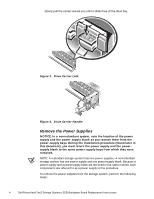
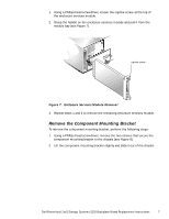
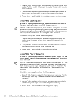
Figure 10.
Screw Location
2.
Using a ball-head Allen driver, remove the fifteen screws. Use an
11.5-inch–long, 5/64-inch ball-head Allen driver to remove the screws
located inside the enclosure services module bays on the left and right side
of the chassis (see Figure 11).
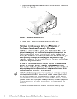
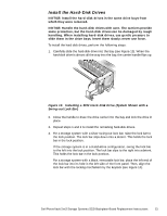
NOTE: A magnetized 11.5-inch–long, 5/64-inch ball-head driver is included
with the SCSI backplane board in the service kit.
Figure 11.
Screw Location in the Left Enclosure Services Module Bay
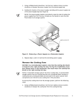
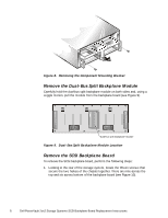
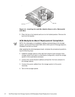
3.
Separate the two chassis halves to remove the backplane board (see
Figure 12).
Figure 12.
Chassis Separation
image shown without chassis
screw
screw
left-side enclosure services
module is shown