Dell PowerVault 51F Dell PowerVault 56F 16-Port Fibre Channel Switch Inst - Page 100
diagClearError, Telnet
 |
View all Dell PowerVault 51F manuals
Add to My Manuals
Save this manual to your list of manuals |
Page 100 highlights
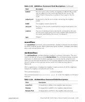
To retest a port which has been marked , clear the port and set to using the diagClearError < > command. This command clears the port status only and does not clear the logs or change the port's condition. The diagClearError < > command should only be used during diagnostic procedures to reset a bad port for retest. For more detailed error message information, see Appendix A, "Error Messages." Telnet commands (see Chapter 4, "PowerVault 56F 16-Port Fibre Channel Switch Commands") are available to determine the switch's status, error conditions, and switch operating statistics. The diagnostic procedures are completed using commands during a Telnet session. Various loopback paths are built into the switch hardware for diagnostic purposes. A loopback path test within the switch verifies the proper internal Fibre Channel Port (FCP) logic functions and the paths between the interfaces and central memory. Error messages are stored in RAM and are lost when power is removed from the switch. Access the error message log to view and note any error messages before removing power from the switch. The following status activity indicators apply to G_Port and FL_Port interface cards. NOTE: FL_Port interface cards have an additional green light-emitting diode (LED) (visible from the front of the switch) to identify them from G_Port interface cards. The color and flash speed of the power LED, as described in Table 5-1, indicates the switch's status. 5-2 Installation and Troubleshooting Guide
-
 1
1 -
2
-
3
-
4
-
5
-
6
-
7
-
8
-
9
-
10
-
11
-
12
-
13
-
14
-
15
-
16
-
17
-
18
-
19
-
20
-
21
-
22
-
23
-
24
-
25
-
26
-
27
-
28
-
29
-
30
-
31
-
32
-
33
-
34
-
35
-
36
-
37
-
38
-
39
-
40
-
41
-
42
-
43
-
44
-
45
-
46
-
47
-
48
-
49
-
50
-
51
-
52
-
53
-
54
-
55
-
56
-
57
-
58
-
59
-
60
-
61
-
62
-
63
-
64
-
65
-
66
-
67
-
68
-
69
-
70
-
71
-
72
-
73
-
74
-
75
-
76
-
77
-
78
-
79
-
80
-
81
-
82
-
83
-
84
-
85
-
86
-
87
-
88
-
89
-
90
-
91
-
92
-
93
-
94
-
 95
95 -
 96
96 -
 97
97 -
 98
98 -
 99
99 -
 100
100 -
 101
101 -
 102
102 -
 103
103 -
 104
104 -
 105
105 -
106
-
107
-
108
-
109
-
110
-
111
-
112
-
113
-
114
-
115
-
116
-
117
-
118
-
119
-
120
-
121
-
122
-
123
-
124
-
125
-
126
-
127
-
128
-
129
-
130
-
131
-
132
-
133
-
134
-
135
-
136
-
137
-
138
-
139
-
140
-
141
-
142
-
143
-
144
-
145
-
146
-
147
-
148
-
149
-
150
-
151
-
152
-
153
-
154
-
155
-
156
-
157
-
158
-
159
-
160
-
161
-
162
-
163
-
164
-
165
-
166
-
167
-
168
-
169
-
170
-
171
-
172
 |
 |
