Dell PowerVault 530F User's Guide - Page 24
Dell PowerVault 530F SAN Appliance User, s Guide, link indicator, activity indicator
 |
View all Dell PowerVault 530F manuals
Add to My Manuals
Save this manual to your list of manuals |
Page 24 highlights
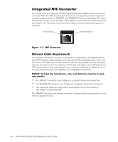
Your system has an integrated 10/100-megabit-per-second (Mbps) network interface controller (NIC). The NIC provides all the functions of a separate network expansion card and supports both the 10BASE-T and 100BASE-TX Ethernet standards. The green link indicator on the connector lights if the adapter is connected to a valid link partner (see Figure 1-3). The amber activity indicator lights if network data is being sent or received. link indicator activity indicator Your system's RJ45 NIC connector is designed for attaching an unshielded twisted pair (UTP) Ethernet cable equipped with standard RJ45-compatible plugs. Press one end of the UTP cable into the NIC connector until the plug snaps securely into place. Connect the other end of the cable to an RJ45 jack wall plate or to an RJ45 port on a UTP concentrator or hub, depending on your network configuration. Observe the following cabling restrictions for 10BASE-T and 100BASE-TX networks. For 10BASE-T networks, use Category 3 or greater wiring and connectors. For 100BASE-TX networks, use Category 5 or greater wiring and connectors. The maximum cable run length (from a workstation to a concentrator) is 100 meters (m) (328 feet [ft]). For 10BASE-T networks, the maximum number of daisy-chained concentrators on one network segment is four. 1-4 Dell PowerVault 530F SAN Appliance User's Guide
-
 1
1 -
2
-
3
-
4
-
5
-
6
-
7
-
8
-
9
-
10
-
11
-
12
-
13
-
14
-
15
-
16
-
17
-
18
-
 19
19 -
 20
20 -
 21
21 -
 22
22 -
 23
23 -
 24
24 -
 25
25 -
 26
26 -
 27
27 -
 28
28 -
 29
29 -
30
-
31
-
32
-
33
-
34
-
35
-
36
-
37
-
38
-
39
-
40
-
41
-
42
-
43
-
44
-
45
-
46
-
47
-
48
-
49
-
50
-
51
-
52
-
53
-
54
-
55
-
56
 |
 |
