Dell PowerVault MD1220 Setting Up Your Dell PowerVault Storage Enclosure - Page 1
Dell PowerVault MD1220 Manual
 |
View all Dell PowerVault MD1220 manuals
Add to My Manuals
Save this manual to your list of manuals |
Page 1 highlights
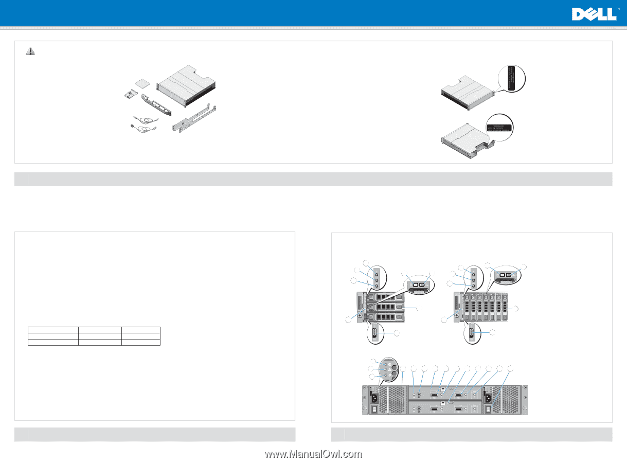
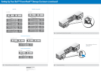
Setting Up Your Dell™ PowerVault™ Storage Enclosure WARNING: Before you set up and operate your Dell PowerVault system, review the safety instructions that came with your system. Verify Package Contents • Storage enclosure • SAS cables (2) • Power cables (2) • Bezel (optional) • Mounting rails (2) (optional) • RAID controller card (optional) • User documentation Install the Enclosure in a Rack The enclosure requires a properly grounded electrical outlet, a compatible rack, and a rack installation kit. For information about installing the rails, see the Rack Installation Instructions that shipped with your rail kit. Locating Your System Service Tag • Your system is identified by a unique Express Service Code and Service Tag number. The Express Service Code and Service Tag are found on the front of the enclosure. • The Service Tag is also located at the back of the system next to the enclosure management modules. • This information is used by Dell to route support calls to the appropriate personnel. 1 Before You Begin Check for documentation and information updates on support.dell.com/manuals. Always read the updates first because they often supersede information in other documents. Cabling Your Enclosure for Unified or Split Mode Configuration You can cable your enclosure in either a unified-mode configuration or in a split-mode configuration. • In a unified-mode configuration, your enclosure is connected to one host; for example, a server with a controller card. Your enclosure can be one of up to four enclosures daisy-chained to a single port on the controller card in your host server. The enclosure can also be connected in a redundant path mode with two connections to a single host server. • In a split-mode configuration, your enclosure is connected to two separate controller cards. The controller cards may reside in the same server or in two different servers. The enclosure bus is logically split in half where the first half of the enclosure is managed by one controller and the second half of the enclosure is managed by the second controller . The table below lists the drives that are controlled by each enclosure management module (EMM) in a split-mode configuration. Enclosure Dell PowerVault MD1200 Dell PowerVault MD1220 EMM 0 Drives 6 to 11 Drives 12 to 23 EMM 1 Drives 0 to 5 Drives 0 to 11 NOTE: Split-mode configurations do not support daisy-chaining of enclosures and redundant paths. The operating mode is selected using the enclosure mode switch on the front panel of the enclosure. NOTE: The enclosure mode switch must be set to either unified mode or split mode before the enclosure is turned on. Changing the configuration mode after turning on the enclosure has no effect on the enclosure configuration until the enclosure is rebooted. For examples of supported cable configurations, see "Cabling the Enclosures to the Host Server(s)" below. For more information about cabling your enclsoure, see the Dell™ PowerVault™ MD1200 and MD1220 Storage Enclosures Hardware Owner's Manual at support.dell.com/manuals. 2 Selecting the Operating Mode Front-Panel Features Dell PowerVault MD1200 3 2 4 1 Dell PowerVault MD1220 3 4 5 5 2 1 8 Back-Panel Features 1 2 3 6 8 7 6 7 4 5 6 7 8 9 10 11 12 13 14 3 Identifying Ports and Connectors on Your Enclosure 1. Split mode LED 2. Power LED 3. Enclosure status LED 4. Hard-drive activity indicator 5. Hard-drive status indicator 6. Hard drives 7. Enclosure-mode switch 8. System identification button 1. DC power LED 2. Power supply/cooling fan fault LED 3. AC power LED 4. Power supply/cooling fan module 1 5. System identification indicator 6. Debug port 7. Enclosure Management Module 1 8. SAS port (In) 9. In port link status LED 10. Enclosure Management Module 0 11. SAS port (Out) 12. Out port link status LED 13. EMM status LED 14. Power switches (2)
-
 1
1 -
 2
2
 |
 |