Dell Vostro 14 3449 Owners Manual - Page 27
Removing the Camera
 |
View all Dell Vostro 14 3449 manuals
Add to My Manuals
Save this manual to your list of manuals |
Page 27 highlights
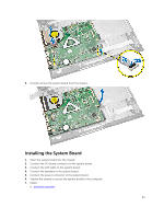
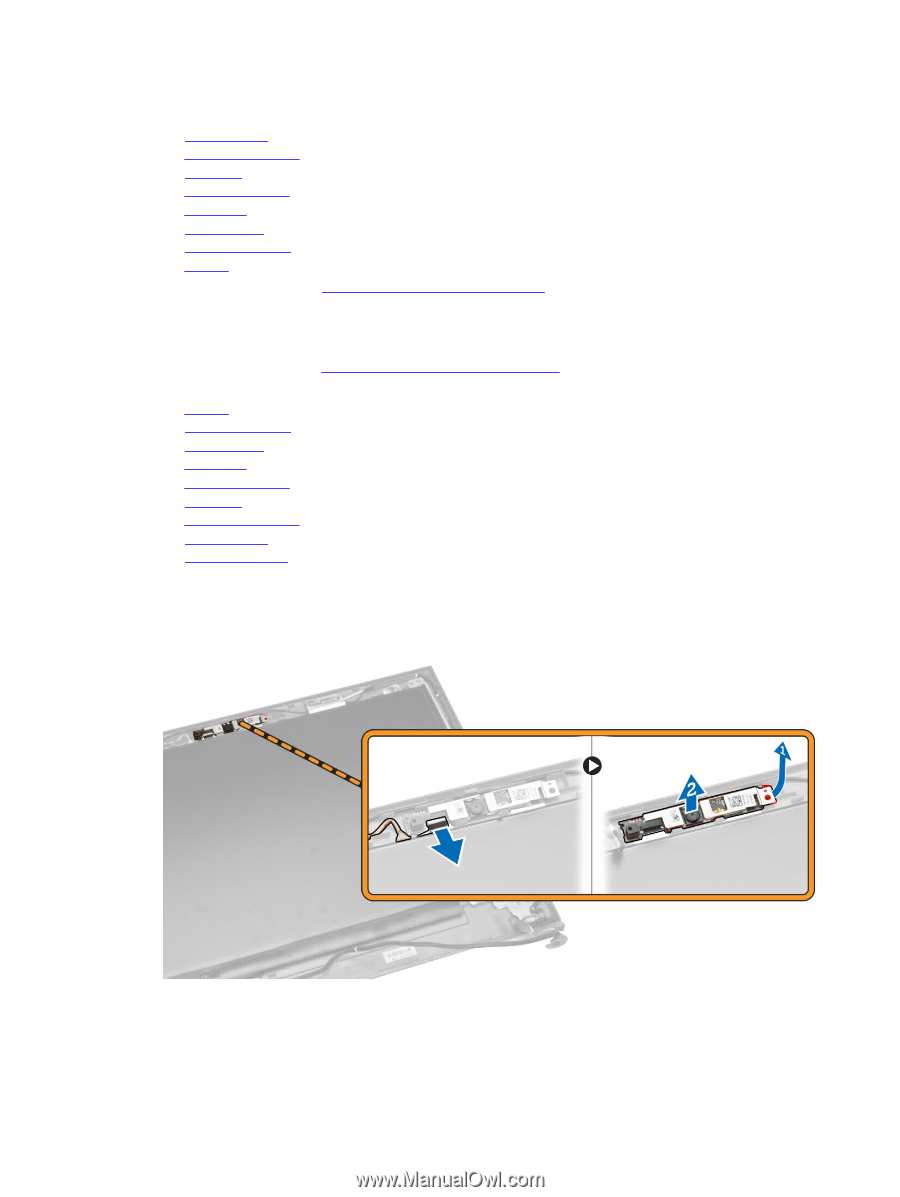
6. Install: a. system board b. palmrest assembly c. keyboard d. memory module e. hard drive f. access panel g. optical disk-drive h. battery 7. Follow the procedures in After Working Inside Your computer. Removing the Camera 1. Follow the procedures in Before Working Inside Your Computer. 2. Remove: a. battery b. optical disk-drive c. access panel d. hard drive e. memory module f. keyboard g. palmrest assembly h. system board i. display assembly 3. Perform the following steps as shown in the illustration: a. Disconnect the camera cable from the camera. b. Release the retention tab from the display assembly [1]. c. Remove the camera from the display assembly [2]. 27
-
 1
1 -
2
-
3
-
4
-
5
-
6
-
7
-
8
-
9
-
10
-
11
-
12
-
13
-
14
-
15
-
16
-
17
-
18
-
19
-
20
-
21
-
 22
22 -
 23
23 -
 24
24 -
 25
25 -
 26
26 -
 27
27 -
 28
28 -
 29
29 -
 30
30 -
 31
31 -
 32
32 -
33
-
34
-
35
-
36
-
37
-
38
-
39
-
40
-
41
-
42
-
43
-
44
-
45
 |
 |
6.
Install:
a.
system board
b.
palmrest assembly
c.
keyboard
d.
memory module
e.
hard drive
f.
access panel
g.
optical disk-drive
h.
battery
7.
Follow the procedures in
After Working Inside Your computer
.
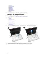
Removing the Camera
1.
Follow the procedures in
Before Working Inside Your Computer
.
2.
Remove:
a.
battery
b.
optical disk-drive
c.
access panel
d.
hard drive
e.
memory module
f.
keyboard
g.
palmrest assembly
h.
system board
i.
display assembly
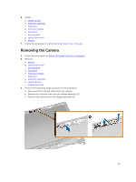
3.
Perform the following steps as shown in the illustration:
a.
Disconnect the camera cable from the camera.
b.
Release the retention tab from the display assembly [1].
c.
Remove the camera from the display assembly [2].
27