Dell Vostro 3583 Service Manual
Dell Vostro 3583 Manual
 |
View all Dell Vostro 3583 manuals
Add to My Manuals
Save this manual to your list of manuals |
Dell Vostro 3583 manual content summary:
- Dell Vostro 3583 | Service Manual - Page 1
Dell Vostro 3583 Service Manual Regulatory Model: P75F Regulatory Type: P75F010 - Dell Vostro 3583 | Service Manual - Page 2
of data and tells you how to avoid the problem. WARNING: A WARNING indicates a potential for property damage, personal injury, or death. © 2019 Dell Inc. or its subsidiaries. All rights reserved. Dell, EMC, and other trademarks are trademarks of Dell Inc. or its subsidiaries. Other trademarks may be - Dell Vostro 3583 | Service Manual - Page 3
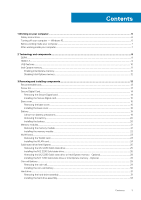
instructions...6 Turning off your computer - Windows 10...6 Before working inside your computer...7 After working inside your computer...7 2 Technology and components...8 DDR4...8 HDMI 1.4...9 USB features...10 Intel Optane memory...11 Enabling Intel Optane memory...12 Disabling Intel Optane memory - Dell Vostro 3583 | Service Manual - Page 4
System fan...35 Removing the system fan...35 Installing the system fan...37 Heat sink...39 Removing the heatsink...39 Installing the heatsink...39 Speakers...40 Removing the speakers...40 Installing the speakers...41 IO board...42 Removing the IO board...42 Installing the IO board...44 Touchpad...45 - Dell Vostro 3583 | Service Manual - Page 5
Installing the display back-cover...79 Palm-rest and keyboard assembly...80 Removing the palmrest and keyboard assembly...80 4 Troubleshooting...82 Enhanced Pre-Boot System Assessment (ePSA) diagnostics 82 power cycle...84 Flea power release...84 5 Getting help...85 Contacting Dell...85 Contents 5 - Dell Vostro 3583 | Service Manual - Page 6
computer, replace all troubleshooting and simple repairs as authorized in your product documentation, or as directed by the online or telephone service and support team. Damage due to servicing that is not authorized by Dell is not covered by your warranty. Read and follow the safety instructions - Dell Vostro 3583 | Service Manual - Page 7
working inside the computer. Steps 1. Ensure that you follow the Safety Instruction. 2. Ensure that your work surface is flat and clean to After working inside your computer About this task After you complete any replacement procedure, ensure that you connect any external devices, cards, and cables - Dell Vostro 3583 | Service Manual - Page 8
1.2 volts, compared to DDR3 which requires 1.5 volts of electrical power to operate. DDR4 also supports a new, deep power-down mode that allows the host device to go into standby without needing to refresh its memory. Deep power-down mode is expected to reduce standby power consumption by 40 to 50 - Dell Vostro 3583 | Service Manual - Page 9
Troubleshoot for possible memory failure by trying known good memory modules in the memory connectors on the bottom of the system or under the keyboard, as in some portable systems. NOTE: The DDR4 memory is imbedded in board and not a replaceable provisions. HDMI supports standard, enhanced, - Dell Vostro 3583 | Service Manual - Page 10
simplified the connection between host computers and peripheral devices like mice, keyboards, external drivers, and printers. Let's take a quick look on the devices • New power management features • Full-duplex data transfers and support for new transfer types • Backward USB 2.0 compatibility • New - Dell Vostro 3583 | Service Manual - Page 11
continue to require separate drivers for USB 3.0/USB 3.1 Gen 1 controllers. Intel Optane memory Intel Optane memory functions only as a storage accelerator. It neither replaces nor adds to the memory (RAM) installed on your computer. NOTE: Intel Optane memory is supported on computers that meet - Dell Vostro 3583 | Service Manual - Page 12
Generation or higher Intel Core i3/i5/i7 processor • Windows 10 64-bit version 1607 or higher • Intel Rapid Storage Technology driver version 15.9.1.1018 or higher Table 2. Intel Optane memory specifications Feature Interface Connector Configurations supported Capacity Specifications PCIe 3x2 NVMe - Dell Vostro 3583 | Service Manual - Page 13
procedures in this document require the following tools: • Phillips #0 screwdriver • Phillips #1 screwdriver • Plastic scribe NOTE: The #0 screw driver is for screws 0-1 and the #1 screw driver is for screws 2-4. Screw list The table provides the list of screws that are used for securing different - Dell Vostro 3583 | Service Manual - Page 14
Component Power button with fingerprint reader (optional) System board Power-adapter port Display panel Hinges Screw type M2x2 Big Head M2x4 M2x3 M2x2 M2.5x2.5 M2x2 Quantity 1 1 1 4 8 2 Wireless-card bracket M2x3 1 Secure Digital Card Removing the Secure Digital card Prerequisites 1. Follow - Dell Vostro 3583 | Service Manual - Page 15
Installing the Secure Digital card Steps 1. Slide the secure digital into the slot until it clicks into place. 2. Follow the procedures in After working inside your computer. Removing and installing components 15 - Dell Vostro 3583 | Service Manual - Page 16
the procedure in before working inside your computer 2. Remove the SD memory card Steps 1. Loosen the three captive screws [1]. 2. Remove the six (M2.5x7) screws and single (M2x4) screw that secure the base cover to the palmrest and keyboard assembly [2, 3]. 16 Removing and installing components - Dell Vostro 3583 | Service Manual - Page 17
3. Pry the base cover from the top-left corner [1] and continue to pry open the sides of the base cover [2, 3, 4]. Removing and installing components 17 - Dell Vostro 3583 | Service Manual - Page 18
edges and sides of the base cover until it snaps into place [2, 3]. 3. Tighten the three captive screws, and replace the single (M2x4) screw that secures the base cover to the palmrest and keyboard assembly [1, 2]. 4. Replace the six (M2.5x7) screws that secure the base cover to the palmrest and - Dell Vostro 3583 | Service Manual - Page 19
Replace the SD memory on or against the battery. • Ensure any screws during the servicing of this product are not lost or misplaced, to prevent accidental Dell technical support for assistance. See www.dell.com/contactdell. • Always purchase genuine batteries from www.dell.com or authorized Dell - Dell Vostro 3583 | Service Manual - Page 20
memory card 3. Remove the base cover Steps 1. Disconnect the battery cable from the system board [1]. 2. Remove the four (M2x3) screws that secure the battery to the palmrest and keyboard keyboard assembly [1]. 2. Replace the four (M2x3) screws that secure the battery to the palmrest and keyboard - Dell Vostro 3583 | Service Manual - Page 21
Next steps 1. Replace the base cover 2. Replace the SD memory card 3. Follow the procedure in after working inside your computer Memory modules Removing the memory module Prerequisites 1. Follow the procedure in before working inside your computer 2. Remove the SD memory card 3. Remove the base - Dell Vostro 3583 | Service Manual - Page 22
1. Align the notch on the memory module with the tab on the memory-module slot. 2. Slide the memory module firmly into the slot at an angle [1]. 3. Press the memory module down until the clips secure it [2]. NOTE: If you do not hear the click, remove the memory module and reinstall it. 22 Removing - Dell Vostro 3583 | Service Manual - Page 23
Next steps 1. Connect the battery cable to the connector on the system board. 2. Replace the base cover 3. Replace the SD memory card 4. Follow the procedure in after working inside your computer WLAN card Removing the WLAN card Prerequisites 1. Follow the procedure in before working inside your - Dell Vostro 3583 | Service Manual - Page 24
[1]. 2. Connect the WLAN cables to the connectors on the WLAN card [2]. 3. Place the WLAN card bracket to secure the WLAN cables to the WLAN card [3]. 4. Replace the single (M2x3) screw to secure the WLAN bracket to the WLAN card [4]. 24 Removing and installing components - Dell Vostro 3583 | Service Manual - Page 25
cable to the connector on the system board. 2. Replace the base cover 3. Replace the SD memory card 4. Follow the procedure in after working inside the palmrest and keyboard assembly [1]. 2. Remove the single (M2x3) screw that secures the thermal plate to the palmrest and keyboard assembly [2]. 3. - Dell Vostro 3583 | Service Manual - Page 26
the solid-state drive off the thermal plate [2]. Installing the M.2 2230 Solid-state drive Steps 1. Place the solid-state drive into the thermal plate slot [1]. 2. Replace the single (M2x2) screw that secures the solid-state drive to the thermal plate [2]. 26 Removing and installing components - Dell Vostro 3583 | Service Manual - Page 27
single (M2x3) screw that secures the thermal plate to the palmrest and keyboard assembly [3]. Next steps 1. Connect the battery cable to the connector on the system board. 2. Replace the base cover 3. Replace the SD memory card 4. Follow the procedure in after working inside your computer Removing - Dell Vostro 3583 | Service Manual - Page 28
drive/Intel Optane off the palmrest and keyboard assembly [4]. Installing the M.2 2280 Solid-state drive or Intel Optane memory - Optional Steps 1. Slide and insert thermal plate to the palmrest and keyboard assembly [3]. 3. Replace the single (M2x3) screw that secures the thermal plate to the - Dell Vostro 3583 | Service Manual - Page 29
2. Replace the base cover 3. Replace the SD memory card memory card 3. Remove the base cover 4. Disconnect the battery cable from the connector on the system board. Steps 1. Disconnect the coin-cell battery cable from the I/O board [1]. 2. Peel the coin-cell battery from the palm rest and keyboard - Dell Vostro 3583 | Service Manual - Page 30
Installing the coin-cell battery Steps 1. Connect the coin-cell battery cable to the I/O board [1]. 2. Affix the coin cell battery on the palm rest and keyboard assembly [2]. 30 Removing and installing components - Dell Vostro 3583 | Service Manual - Page 31
to the connector on the system board. 2. Replace the base cover 3. Replace the SD memory card 4. Follow the procedure in after working inside to the palm rest and keyboard assembly [2]. 3. Lift the hard drive assembly along with its cable off the palm rest and keyboard assembly [3]. Removing and - Dell Vostro 3583 | Service Manual - Page 32
4. Disconnect the interposer from the hard drive. 5. Remove the four (M3x3) screws that secure the hard drive bracket to the hard drive [1]. 6. Lift the hard drive bracket off the hard drive [2]. 32 Removing and installing components - Dell Vostro 3583 | Service Manual - Page 33
Installing the hard drive assembly Steps 1. Align the screw holes on the hard drive bracket with the screw holes on the hard drive [1]. 2. Replace the four (M3x3) screws that secure the hard drive bracket to the hard drive [2]. 3. Connect the interposer to the hard drive. Removing and installing - Dell Vostro 3583 | Service Manual - Page 34
hard drive assembly to the palm rest and keyboard assembly [2]. 6. Connect the hard drive cable to the system board and close the latch to secure the cable [3]. Next steps 1. Replace the battery 2. Replace the base cover 3. Replace the SD memory card 4. Follow the procedure in after working inside - Dell Vostro 3583 | Service Manual - Page 35
System fan Removing the system fan Prerequisites 1. Follow the procedure in before working inside your computer 2. Remove the SD memory card 3. Remove the base cover 4. Disconnect the battery cable from the connector on the system board. Steps 1. Disconnect the display cable and fan cable from - Dell Vostro 3583 | Service Manual - Page 36
3. Remove the three (M2.5x5) screws that secure the fan to the palm rest and keyboard board assembly [1]. 4. Lift the fan off the palm rest and keyboard board assembly [2]. 36 Removing and installing components - Dell Vostro 3583 | Service Manual - Page 37
on the fan with the screw holes on the palm rest and keyboard board assembly [1]. 2. Replace the three (M2.5x5) screws that secure the fan to the palm rest and keyboard board assembly [2]. 3. Route the display cable through the routing guides on the fan [1]. Removing and installing components 37 - Dell Vostro 3583 | Service Manual - Page 38
4. Connect the display cable and fan cable to the system board [1, 2]. Next steps 1. Replace the battery 2. Replace the base cover 3. Replace the SD memory card 38 Removing and installing components - Dell Vostro 3583 | Service Manual - Page 39
after working inside your computer Heat sink Removing the heatsink Prerequisites 1. Follow the procedure in before working inside your computer 2. Remove the SD memory card 3. Remove the base cover 4. Remove the battery 5. Remove the system fan Steps 1. Loosen the four captive screws that secure the - Dell Vostro 3583 | Service Manual - Page 40
your computer 2. Remove the SD memory card 3. Remove the base cover 4. Remove the battery 5. Remove the SSD Steps 1. Disconnect the speaker cable from the system board [1]. 2. Unroute and remove the speaker cable from the routing guides on palm rest and keyboard assembly [2]. 3. Lift the speakers - Dell Vostro 3583 | Service Manual - Page 41
them back in before replacing the speakers. Steps 1. Using the alignment posts and rubber grommets, place the speakers in the slots on the palm rest and keyboard assembly [1]. 2. Route the speaker cable through the routing guides on the palm rest and keyboard assembly [2]. 3. Connect the speaker - Dell Vostro 3583 | Service Manual - Page 42
1. Replace the SSD 2. Replace the battery 3. Replace the base cover 4. Replace the SD memory card 5. Follow the procedure in after working inside your computer IO board Removing the IO board Prerequisites 1. Follow the procedure in before working inside your computer 2. Remove the SD memory card - Dell Vostro 3583 | Service Manual - Page 43
3. Remove the two (M2x4) screws that secure the I/O board to the palm rest and keyboard assembly [1]. 4. Lift the I/O board, along with the cable, off the palm rest and keyboard assembly [2]. Removing and installing components 43 - Dell Vostro 3583 | Service Manual - Page 44
board Steps 1. Using the alignment posts, place the I/O board on the palm rest and keyboard assembly [1]. 2. Replace the two (M2x4) screws that secure the I/O board to the palm rest and keyboard assembly [2]. 3. Connect the coin-cell battery cable to the I/O board [1]. 4. Connect the I/O board cable - Dell Vostro 3583 | Service Manual - Page 45
the hard drive assembly 2. Replace the battery 3. Replace the base cover 4. Replace the SD memory card 5. Follow the procedure in after working inside your computer Touchpad Removing the touch pad assembly Prerequisites 1. Follow the procedure in before working inside your - Dell Vostro 3583 | Service Manual - Page 46
that secure the touch pad bracket to the palmrest and keyboard assembly [1]. 4. Lift the touch pad bracket off the palm rest and keyboard assembly [2]. 5. Remove the four (M2x2) screws that secure the touch pad to the palmrest and keyboard assembly [1]. 6. Lift the touch pad off the palmrest and - Dell Vostro 3583 | Service Manual - Page 47
Ensure that the touch pad is aligned with the guides available on the palm-rest and keyboard assembly, and the gap on either sides of the touch pad is equal. Steps 1. Place the touch pad into the slot on the palmrest and keyboard assembly [1]. 2. Replace the four (M2x2) screws that secure the touch - Dell Vostro 3583 | Service Manual - Page 48
pad bracket into the slot on the palmrest and keyboard assembly [1]. 4. Replace the two screws (M2x2) that secure the touch pad bracket to the palmrest and keyboard assembly [2]. 5. Affix the tape that secures the touch pad to the palmrest and keyboard assembly [1]. 6. Slide the touch pad cable and - Dell Vostro 3583 | Service Manual - Page 49
the SD memory card 3. Remove the base cover 4. Disconnect the battery cable from the connector on the system board 5. Remove the WLAN Steps 1. Open the latch and disconnect the display cable from the system board [1]. 2. Unroute the display cable from the routing guides on the palmrest and keyboard - Dell Vostro 3583 | Service Manual - Page 50
screws that secure the left and right hinges to the system board, and palmrest and keyboard assembly [1]. 5. Lift the palmrest and keyboard assembly at an angle [2]. 6. Lift the hinges. Remove the palmrest and keyboard assembly off the display assembly [1, 2] 50 Removing and installing components - Dell Vostro 3583 | Service Manual - Page 51
7. After performing all the preceding steps, you are left with display assembly. Removing and installing components 51 - Dell Vostro 3583 | Service Manual - Page 52
the display assembly About this task NOTE: Ensure that the hinges are opened to the maximum before replacing the display assembly on the palmrest and keyboard assembly. Steps 1. Align and place the palmrest and keyboard assembly under the hinges on the display assembly [1]. 2. Seat the palmrest and - Dell Vostro 3583 | Service Manual - Page 53
5. Route the display cable through the routing guides on the palmrest and keyboard assembly [1]. 6. Connect the display cable to the connector on the system board [2]. 7. Affix the antenna cables to the system board [3]. Removing and installing components 53 - Dell Vostro 3583 | Service Manual - Page 54
cable to the connector on the system board. 3. Replace the base cover 4. Replace the SD memory card 5. Follow the procedure in after working inside your secures the power button board to the palmrest and keyboard assembly [3]. 4. Lift the power button board, along with the cable off the palmrest - Dell Vostro 3583 | Service Manual - Page 55
board Steps 1. Place the power-button board into the slot on the palmrest and keyboard assembly [1]. 2. Replace the single (M2x2) screw that secures the power button board to the palmrest and keyboard assembly [2]. 3. Affix the conductive tape to the power button board [3]. 4. Slide the power button - Dell Vostro 3583 | Service Manual - Page 56
with fingerprint reader Steps 1. Affix the fingerprint reader cable on the palm rest and keyboard assembly. 2. Using the alignment posts, align and place the power button on the palmrest and keyboard assembly [1]. 3. Replace the single (M2x2) screw that secures the power button on the palmrest and - Dell Vostro 3583 | Service Manual - Page 57
the battery cable to the connector on the system board. 6. Replace the base cover 7. Replace the SD memory card 8. Follow the procedure in after working inside your computer screw that secures the power button on the palmrest and keyboard assembly [1]. 2. Lift the power button off the palmrest and - Dell Vostro 3583 | Service Manual - Page 58
Installing the power button Steps 1. Place the power-button into the slot on the palmrest and keyboard assembly [1]. 2. Replace the single (M2x2) screw that secures the power button on the palmrest and keyboard assembly [2]. 58 Removing and installing components - Dell Vostro 3583 | Service Manual - Page 59
cable to the connector on the system board. 6. Replace the base cover 7. Replace the SD memory card 8. Follow the procedure in after working inside Remove the SD memory card 3. Remove the base cover 4. Remove the battery 5. Remove the memory 6. Remove the WLAN 7. Remove the SSD 8. Remove the system - Dell Vostro 3583 | Service Manual - Page 60
Disconnect the following cables from the system board: a) Power button board cable [1]. b) Finger print board cable [2]. c) IO board cable [3]. d) Hard drive cable [4]. e) Touchpad cable [5]. f) Keyboard cable [6]. 3. Remove the single (M2x4) screw that secures the system board to the palmrest and - Dell Vostro 3583 | Service Manual - Page 61
Installing the system board Steps 1. Align the screw hole on the system board with the screw hole on the palmrest and keyboard assembly [1]. 2. Replace the single (M2x4) screw that secures the system board to the palmrest and keyboard assembly [2]. Removing and installing components 61 - Dell Vostro 3583 | Service Manual - Page 62
3. Connect the following cables to the system board: a) Power button board cable [1]. b) Finger print board cable [2]. c) IO board cable [3]. d) Hard drive cable [4]. e) Touchpad cable [5]. f) Keyboard cable [6]. 62 Removing and installing components - Dell Vostro 3583 | Service Manual - Page 63
4. Connect the power adapter port cable and speaker cable to the system board [1, 2]. Next steps 1. Replace the display assembly 2. Replace the heatsink 3. Replace the system fan 4. Replace the SSD Removing and installing components 63 - Dell Vostro 3583 | Service Manual - Page 64
the WLAN 6. Replace the memory 7. Replace the battery 8. Replace the base cover 9. Replace the SD memory card 10. Follow the procedure in after working inside your computer Power-adapter port Removing the power adapter port Prerequisites 1. Follow the procedure in before - Dell Vostro 3583 | Service Manual - Page 65
keyboard assembly [1]. 2. Replace the single (M2x3) screw that secures the power adapter port to the palmrest and keyboard Replace the power button board 2. Replace the display assembly 3. Replace the SSD 4. Replace the WLAN 5. Replace the battery 6. Replace the base cover 7. Replace the SD memory - Dell Vostro 3583 | Service Manual - Page 66
5. Remove the memory 6. Remove the WLAN 7. Remove the SSD 8. Remove the hard drive assembly 9. Remove the system fan 10. Remove the heatsink 11. Remove the display assembly Steps 1. Pry the inner top side of - Dell Vostro 3583 | Service Manual - Page 67
Next steps 1. Replace the display assembly 2. Replace the hard drive assembly 3. Replace the system fan 4. Replace the heatsink 5. Replace the SSD 6. Replace the WLAN 7. Replace the memory 8. Connect the battery cable to the connector on the system board. 9. Replace the base cover 10. Replace the SD - Dell Vostro 3583 | Service Manual - Page 68
11. Remove the display bezel Steps 1. Using a plastic scribe, gently pry the camera off the display back-cover and antenna assembly [1]. 2. Disconnect the camera cable from the camera module [2]. 3. Lift the camera module from the display back-cover and antenna assembly [3]. Installing the camera - Dell Vostro 3583 | Service Manual - Page 69
Next steps 1. Replace the display bezel 2. Replace the display assembly 3. Replace the hard drive assembly 4. Replace the system fan 5. Replace the heatsink 6. Replace the SSD 7. Replace the WLAN 8. Replace the battery 9. Replace the base cover 10. Replace the SD memory card 11. Follow the procedure - Dell Vostro 3583 | Service Manual - Page 70
8. Remove the system fan 9. Remove the heatsink 10. Remove the display assembly 11. Remove the display bezel 12. Remove the camera Steps 1. Remove the four (M2x2) screws that secure the display panel to the display back-cover and antenna assembly [1]. 2. Lift the display panel and turn it over [2]. - Dell Vostro 3583 | Service Manual - Page 71
Installation display panel Steps 1. Place the display panel on a flat and clean surface [1]. 2. Connect the display cable to the connector at the back of the display panel and close the latch to secure the cable [2]. 3. Adhere the tape that secures the display cable to the back of the display panel - Dell Vostro 3583 | Service Manual - Page 72
5. Align the screw holes on the display panel with the screw holes on the display back-cover and antenna assembly. 6. Replace the four (M2x2) screws that secure the display panel to the display back-cover and antenna assembly [1]. 72 Removing and installing components - Dell Vostro 3583 | Service Manual - Page 73
steps 1. Replace the camera 2. Replace the display bezel 3. Replace the display assembly 4. Replace the hard drive assembly 5. Replace the system fan 6. Replace the heatsink 7. Replace the SSD 8. Replace the WLAN 9. Replace the battery 10. Replace the base cover 11. Replace the SD memory card 12 - Dell Vostro 3583 | Service Manual - Page 74
display hinges Steps 1. Align the screw holes on the hinges and brackets with the screw holes on the display back-cover and antenna assembly [1]. 2. Replace the eight (M2.5x2.5) screws and two (M2x2) screws that secure the hinges to the display back-cover and antenna assembly [3,2 ]. 74 Removing - Dell Vostro 3583 | Service Manual - Page 75
panel 2. Replace the camera 3. Replace the display bezel 4. Replace the display assembly 5. Replace the hard drive assembly 6. Replace the system fan 7. Replace the heatsink 8. Replace the SSD 9. Replace the WLAN 10. Replace the battery 11. Replace the base cover 12. Replace the SD memory card 13 - Dell Vostro 3583 | Service Manual - Page 76
6. Remove the SSD 7. Remove the hard drive assembly 8. Remove the system fan 9. Remove the secures the camera cable [2]. 3. Remove the camera cable and the display cable from the routing guides on the display back-cover and antenna assembly[3] Installing the display cable Steps 1. Route the camera - Dell Vostro 3583 | Service Manual - Page 77
the display panel 3. Replace the display bezel 4. Replace the display assembly 5. Replace the hard drive assembly 6. Replace the system fan 7. Replace the heatsink 8. Replace the SSD 9. Replace the WLAN 10. Replace the battery 11. Replace the base cover 12. Replace the SD memory card 13. Follow the - Dell Vostro 3583 | Service Manual - Page 78
7. Remove the hard drive assembly 8. Remove the system fan 9. Remove the heatsink 10. Remove the display assembly 11. Remove the display bezel 12. Remove the camera 13. Remove the display panel 14. Remove the display hinges 15. Remove the display cable About this task After performing all the - Dell Vostro 3583 | Service Manual - Page 79
panel 4. Replace the camera 5. Replace the display bezel 6. Replace the display assembly 7. Replace the hard drive assembly 8. Replace the system fan 9. Replace the heatsink 10. Replace the SSD 11. Replace the WLAN 12. Replace the battery 13. Replace the base cover 14. Replace the SD memory card 15 - Dell Vostro 3583 | Service Manual - Page 80
assembly Removing the palmrest and keyboard assembly Prerequisites 1. Follow the procedure in before working inside your computer 2. Remove the SD memory card 3. Remove the base cover 4. Remove the battery 5. Remove the memory 6. Remove the WLAN 7. Remove the SSD 8. Remove the speakers 9. Remove the - Dell Vostro 3583 | Service Manual - Page 81
Removing and installing components 81 - Dell Vostro 3583 | Service Manual - Page 82
4 Troubleshooting Enhanced successfully • View error messages that inform you of problems encountered during testing NOTE: Some tests for specific devices the computer boots, press the F12 key as the Dell logo appears. 3. On the boot menu screen, select the Diagnostics option. 4. Click the arrow at - Dell Vostro 3583 | Service Manual - Page 83
SLN143196 at www.dell.com/support. 3. Copy the instructions on the screen to complete the BIOS update. Flashing the BIOS About this task You may need to flash (update) the BIOS when an update is available or when you replace the system board. Follow these steps to flash the BIOS: Troubleshooting - Dell Vostro 3583 | Service Manual - Page 84
-click the BIOS update file icon and follow the instructions on the screen. Backup media and recovery options It is recommended to create a recovery drive to troubleshoot and fix problems that may occur with Windows. Dell proposes multiple options for recovering Windows operating system on your - Dell Vostro 3583 | Service Manual - Page 85
. Availability varies by country and product, and some services may not be available in your area. To contact Dell for sales, technical support, or customer service issues: Steps 1. Go to Dell.com/support. 2. Select your support category. 3. Verify your country or region in the Choose a Country
-
 1
1 -
 2
2 -
 3
3 -
 4
4 -
 5
5 -
 6
6 -
 7
7 -
8
-
9
-
10
-
11
-
12
-
13
-
14
-
15
-
16
-
17
-
18
-
19
-
20
-
21
-
22
-
23
-
24
-
25
-
26
-
27
-
28
-
29
-
30
-
31
-
32
-
33
-
34
-
35
-
36
-
37
-
38
-
39
-
40
-
41
-
42
-
43
-
44
-
45
-
46
-
47
-
48
-
49
-
50
-
51
-
52
-
53
-
54
-
55
-
56
-
57
-
58
-
59
-
60
-
61
-
62
-
63
-
64
-
65
-
66
-
67
-
68
-
69
-
70
-
71
-
72
-
73
-
74
-
75
-
76
-
77
-
78
-
79
-
80
-
81
-
82
-
83
-
84
-
85
 |
 |

Dell Vostro 3583
Service Manual
Regulatory Model: P75F
Regulatory Type: P75F010