Dell Vostro A840 Service Manual - Page 26
Memory Module - specification
 |
View all Dell Vostro A840 manuals
Add to My Manuals
Save this manual to your list of manuals |
Page 26 highlights
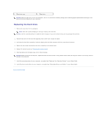
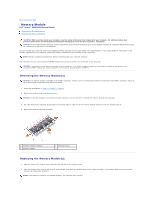
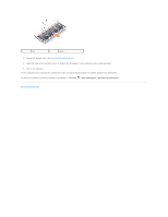
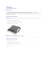
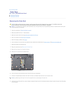
Back to Contents Page Memory Module Dell™ Vostro™ A840/A860 Service Manual Removing the Memory Module(s) Replacing the Memory Module(s) CAUTION: Before working inside your computer, read the safety information that shipped with your computer. For additional safety best practices information, see the Regulatory Compliance Homepage at www.dell.com/regulatory_compliance. NOTICE: To avoid electrostatic discharge, ground yourself by using a wrist grounding strap or by periodically touching an unpainted metal surface (such as a connector on the back of the computer). You can increase your computer memory by installing memory modules on the system board. See "Specifications" in your Setup Guide for information on the memory supported by your computer. Install only memory modules that are intended for your computer. NOTE: Memory modules purchased from Dell are covered under your computer warranty. Your computer has two user-accessible SODIMM sockets that can be accessed from the bottom of the computer. NOTICE: If you need to install memory modules in both connectors, first install a memory module in the connector located at the bottom of the computer (DIMM 1) before you install a module in the connector directly above it (DIMM 2). Removing the Memory Module(s) NOTICE: If a memory module is installed in the DIMM 2 connector, remove it prior to removing the memory module from the DIMM 1 connector. Failure to do so could result in damaging both memory modules. 1. Follow the procedures in "Before You Begin" on page 9. 2. Remove the module cover (see Module Cover). NOTICE: To prevent damage to the memory module connector, do not use tools to spread the memory module securing clips. 3. Use your fingertips to carefully spread apart the securing clips on each end of the memory module connector until the module pops up. 4. Remove the module from the connector. 1 memory module connector 3 memory module 2 securing clip (2) Replacing the Memory Module(s) 1. Align the notch in the module edge connector with the tab in the connector slot. 2. Slide the module firmly into the slot at a 45-degree angle, and rotate the module down until it clicks into place. If the module does not click into place, remove the module and reinstall it. NOTE: If the memory module is not installed properly, the computer may not boot.
-
 1
1 -
2
-
3
-
4
-
5
-
6
-
7
-
8
-
9
-
10
-
11
-
12
-
13
-
14
-
15
-
16
-
17
-
18
-
19
-
20
-
 21
21 -
 22
22 -
 23
23 -
 24
24 -
 25
25 -
 26
26 -
 27
27 -
 28
28 -
 29
29 -
 30
30 -
 31
31 -
32
-
33
-
34
-
35
-
36
 |
 |