Dell W-Series 314 310 Series Access Points Installation Guide - Page 2
Dell Networking 310 Series, Access Points
 |
View all Dell W-Series 314 manuals
Add to My Manuals
Save this manual to your list of manuals |
Page 2 highlights
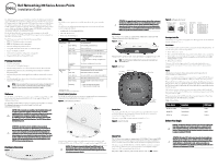
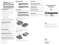
CAUTION: EU Statement: Lower power radio LAN product operating in 2.4 GHz and 5 GHz bands. Please refer to the User Guide for details on restrictions. Produit réseau local radio basse puissance operant dans la bande fréquence 2.4 GHz et 5 GHz. Merci de vous referrer au manuel utilisateur pour les details des restrictions. Low Power FunkLAN Produkt, das im 2.4 GHz und im 5 GHz Band arbeitet. Weitere Informationen bezlüglich Einschränkungen finden Sie im benutzerhandbuch.. Apparati Radio LAN a bassa Potenza, operanti a 2.4 GHz e 5 GHz. Fare riferimento alla manuale utente per avere informazioni detagliate sulle restrizioni. Access Point Pre-Installation Checklist Before installing your 310 Series access point, ensure that you have the following: CAT5E UTP cable or better One of the following power sources: IEEE 802.3at or 802.3af-compliant Power over Ethernet (PoE) source. The PoE source can be any power source equipment (PSE) controller or midspan PSE device Dell AP-AC-V30B AC-to-DC power adapter kit (sold separately) For W-AP314 and W-AP315 access points only: Dell controller provisioned on the network: Layer 2/3 network connectivity to your access point One of the following network services: Aruba Discovery Protocol (ADP) DNS server with an "A" record DHCP Server with vendor-specific options. Note: Dell access points are designed in compliance with governmental requirements, so that only authorized network administrators are permitted to change the settings for this device. For more information about access point configuration, refer to the Quick Start Guide and User Guide for your device. Verifying Pre-Installation Connectivity Note: The instructions for the following section are applicable to W-AP314 and W-AP315 access points only. Before installing access points in a network environment, make sure that they are able to locate and connect to the controller after power on. Specifically, you must verify the following conditions: When connected to the network, each access point is assigned a valid IP address Access points are able to locate the controller Refer to the AOS Quick Start Guide for instructions on locating and connecting to the controller. Pre-Installation Network Requirements After WLAN planning is complete and the appropriate products and their placement have been determined, the Dell controller(s) must be installed and initial setup performed before the Dell access points are deployed. For initial setup of the controller, refer to the AOS Quick Start Guide. Identifying Specific Installation Locations You can mount the 310 Series access point to a wall or on the ceiling. Use the access point placement map generated by the Dell VisualRF Plan software application to determine the proper installation location(s). Each location should be as close as possible to the center of the intended coverage area and should be free from obstructions or obvious sources of interference. These RF absorbers/reflectors/ interference sources will impact RF propagation and should have been accounted for during the planning phase and adjusted for in RF plan. Identifying Known RF Absorbers/Reflectors/Interference Sources Identifying known RF absorbers, reflectors, and interference sources while in the field during the installation phase is critical. Make sure that these sources are taken into consideration when you attach an access point to its fixed location. Examples of sources that degrade RF performance include: Cement and brick Objects that contain water Metal Microwave ovens Wireless phones and headsets Installing the Access Point Refer to the following steps to install your Dell 310 Series access point using the Access Point Ceiling Rail Mount Kit (AP-220-MNT-C1). CAUTION: All Dell access points should be professionally installed by certified technician. The technician is responsible for ensuring that grounding is available that meets applicable regional regulatory and electrical standards. ATTENTION: Tous les points d'accès Dell doivent impérativement être installés par un professionnel agréé. Ce dernier doit s'assurer que l'appareil est mis à la terre et que le circuit de mise à la terre est conforme aux codes électriques nationaux en vigueur. Using the Ceiling Rail Adapter The 310 Series access point includes two ceiling rail adapters for 9/16" and 15/16" ceiling rails. Additional wall mount adapters and ceiling rail adapters for other rail styles are available as accessory kits. CAUTION: The installer is responsible for securing the access point onto the ceiling tile rail in accordance with the steps below. Failure to properly install this product may result in physical injury and/or damage to property. ATTENTION: L'installateur est chargé de sécuriser le point d'accès sur le rail de montage au plafond en suivant la procédure ci-après. Toute installation incorrecte du produit peut entraîner des blessures physiques et/ou des dommages matériels. 1. Pull the necessary cables through a prepared hole in the ceiling tile near where the access point will be placed. 2. Place the adapter against the back of the access point with the adapter at an angle of approximately 30 degrees to the tabs (see Figure 7). 3. Twist the adapter clockwise until it snaps into place in the tabs (see Figure 7). Figure 7 Attaching the Ceiling Rail Adapter 4. If necessary, connect the console cable to the console port on the back of the access point. 5. Hold the access point next to the ceiling tile rail with the ceiling tile rail mounting slots at approximately a 30-degree angle to the ceiling tile rail (see Figure 8). Make sure that any cable slack is above the ceiling tile. 6. Pushing toward the ceiling tile, rotate the access point clockwise until the device clicks into place on the ceiling tile rail. Figure 8 Mounting the Access Point 7. On the W-AP314 and W-IAP314 access points, install the external antennas according to the manufacturer's instructions, and connect the antennas to the antenna interfaces on the access point. Connecting Required Cables Install cables in accordance with all applicable local and national regulations and practices. Verifying Post-Installation Connectivity The integrated LEDs on the access point can be used to verify that the device is receiving power and initializing successfully (see Figure 1). Refer to the AOS Quick Start Guide for further details on verifying post-installation network connectivity. Configuring the 310 Series Note: The instructions for the following section are applicable to W-AP314 and W-AP315 access points only. Access Point Provisioning/Reprovisioning Provisioning parameters are unique to each access point. These local access point parameters are initially configured on the controller which are then pushed out to the access points and stored on the devices. Dell recommends that provisioning settings be configured via the AOS Web UI only. Refer to the AOS User Guide for complete details. Access Point Configuration Configuration parameters are network or controller specific and are configured and stored on the controller. Network configuration settings are pushed out to the access points, but remain stored on the controller. Configuration settings can be configured via the AOS Web UI or CLI. Refer to the respective guides for further details. Dell Networking 310 Series Access Points Installation Guide Contacting Dell Website Support Main Website Contact Information Support Website Documentation Website dell.com dell.com/contactdell dell.com /support dell.com /support/manuals Copyright © Copyright 2016 Hewlett Packard Enterprise Development LP. Dell™, the DELL™ logo, and PowerConnect™ are trademarks of Dell Inc. All rights reserved. Specifications in this manual are subject to change without notice. Originated in the USA. All other trademarks are the property of their respective owners. Open Source Code This product includes code licensed under the GNU General Public License, the GNU Lesser General Public License, and/or certain other open source licenses. You may request a copy of this source code free of charge at [email protected]. Please specify the product and version for which you are requesting source code. dell.com Dell Networking 310 Series Access Points | Installation Guide Part Number 0511904-01| April 2016
-
 1
1 -
 2
2
 |
 |
