Dell XPS /Dimension Gen 2 Owner's Manual - Page 73
System Board Components, Memory, information on the type of memory supported by your computer
 |
View all Dell XPS /Dimension Gen 2 manuals
Add to My Manuals
Save this manual to your list of manuals |
Page 73 highlights
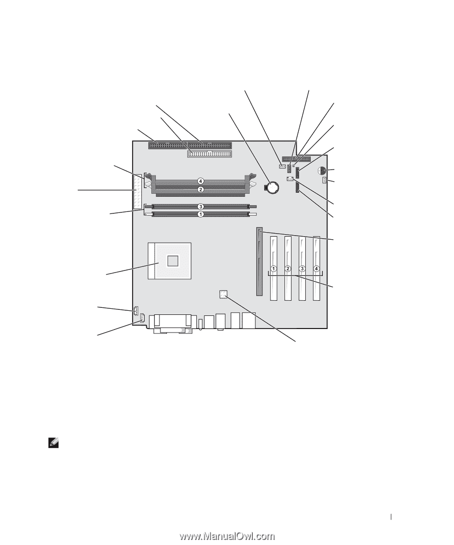
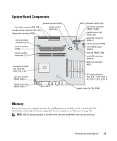
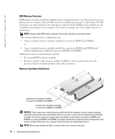
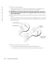
System Board Components password jumper (PASS) hard-drive connector (PRI_IDE) secondary drive connector (SEC_IDE) floppy-drive connector (FDD) battery socket (BATTERY) memory module connectors (2, 4) power connector (PWR) memory module connectors (1, 3) processor and heatsink connector (CPU_PIN_#_A1) rear fan connector (REAR_FAN2) rear fan connector (REAR_FAN1) SCSI_LED header (SCSI_LED) front-panel connector (FRONT_PANEL) standby power light (PWR_LED) serial ATA connector (SATA_1) internal speaker (SPKR) clear CMOS jumper (CMOS) front fan (FRONT_FAN) serial ATA connector (SATA_0) AGP card connector (AGP) PCI card connectors (PCI_SLOT_1, PCI_SLOT_2, PCI_SLOT_3, PCI_SLOT_4) power connector (12V_PWR) Memory You can increase your computer memory by installing memory modules on the system board. For information on the type of memory supported by your computer, see "Memory" on page 105. NOTE: DDR 333 memory operates at 320-MHz when used with an 800-MHz front-side bus processor. Removing and Installing Parts 73
-
 1
1 -
2
-
3
-
4
-
5
-
6
-
7
-
8
-
9
-
10
-
11
-
12
-
13
-
14
-
15
-
16
-
17
-
18
-
19
-
20
-
21
-
22
-
23
-
24
-
25
-
26
-
27
-
28
-
29
-
30
-
31
-
32
-
33
-
34
-
35
-
36
-
37
-
38
-
39
-
40
-
41
-
42
-
43
-
44
-
45
-
46
-
47
-
48
-
49
-
50
-
51
-
52
-
53
-
54
-
55
-
56
-
57
-
58
-
59
-
60
-
61
-
62
-
63
-
64
-
65
-
66
-
67
-
 68
68 -
 69
69 -
 70
70 -
 71
71 -
 72
72 -
 73
73 -
 74
74 -
 75
75 -
 76
76 -
 77
77 -
 78
78 -
79
-
80
-
81
-
82
-
83
-
84
-
85
-
86
-
87
-
88
-
89
-
90
-
91
-
92
-
93
-
94
-
95
-
96
-
97
-
98
-
99
-
100
-
101
-
102
-
103
-
104
-
105
-
106
-
107
-
108
-
109
-
110
-
111
-
112
-
113
-
114
-
115
-
116
-
117
-
118
-
119
-
120
-
121
-
122
-
123
-
124
-
125
-
126
-
127
-
128
-
129
-
130
-
131
-
132
-
133
-
134
-
135
-
136
-
137
-
138
-
139
-
140
-
141
-
142
 |
 |