Dell XPS 14 L401X XPS 14 Service Manual - Page 104
Replacing the System Board
 |
View all Dell XPS 14 L401X manuals
Add to My Manuals
Save this manual to your list of manuals |
Page 104 highlights
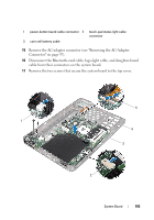
1 logo-light cable connector 3 system board 5 daughter-board cable 2 Bluetooth-card cable connector 4 screws (2) 18 Carefully ease the connectors on the system board out of the slots in the top cover, and lift the system board off the top cover. Replacing the System Board 1 Follow the instructions in "Before You Begin" on page 9. 2 Align the connectors on the system board with the slots on the top cover and place it on the top cover. 3 Replace the two screws that secure the system board to the top cover. 4 Connect the Bluetooth-card cable, logo-light cable, and daughter-board cable to their connectors on the system board. 5 Replace the AC-adapter connector (see "Replacing the AC-Adapter Connector" on page 98). 6 Replace the processor module (see "Replacing the Processor Module" on page 87). 7 Replace the processor fan and heat-sink assembly (see "Replacing the Processor Fan and Heat-Sink Assembly" on page 82). 8 Follow the instructions from step 9 to step 11 in "Replacing the Top Cover" on page 72. 9 Connect the Bluetooth-card cable, logo-light cable, and daughter-board cable to their connectors on the system board. 10 Replace the display assembly (see "Replacing the Display Assembly" on page 55). 11 Replace the keyboard (see "Replacing the Keyboard" on page 43). 12 Replace the palm-rest assembly (see "Replacing the Palm-Rest Assembly" on page 38). 13 Follow the instructions from step 5 to step 6 in "Replacing the Optical Drive" on page 33. 14 Replace the hard drive (see "Replacing the Hard Drive" on page 28). 104 System Board
-
 1
1 -
2
-
3
-
4
-
5
-
6
-
7
-
8
-
9
-
10
-
11
-
12
-
13
-
14
-
15
-
16
-
17
-
18
-
19
-
20
-
21
-
22
-
23
-
24
-
25
-
26
-
27
-
28
-
29
-
30
-
31
-
32
-
33
-
34
-
35
-
36
-
37
-
38
-
39
-
40
-
41
-
42
-
43
-
44
-
45
-
46
-
47
-
48
-
49
-
50
-
51
-
52
-
53
-
54
-
55
-
56
-
57
-
58
-
59
-
60
-
61
-
62
-
63
-
64
-
65
-
66
-
67
-
68
-
69
-
70
-
71
-
72
-
73
-
74
-
75
-
76
-
77
-
78
-
79
-
80
-
81
-
82
-
83
-
84
-
85
-
86
-
87
-
88
-
89
-
90
-
91
-
92
-
93
-
94
-
95
-
96
-
97
-
98
-
 99
99 -
 100
100 -
 101
101 -
 102
102 -
 103
103 -
 104
104 -
 105
105 -
 106
106 -
 107
107 -
 108
108
 |
 |
